I went through this same issue a few years back and read everything I could on the subject until I understood it at the time really well. In reading a lot I found that many articles were poorly written and confusing. I even called a few of the big axle companies and talked to the bosses about the concepts. I have forgotten of lot of what I learned, but I can throw out some of the concepts to keep in mind as you are going through the process.
There are some variables you need to be aware of. Big engines with a lot of torque may have the pinion angle lower or more negative in relation to the drive shaft than smaller engines. This is because as the power is applied the torque will rotate the pinion angle up. So when resting, it would seem to be off, but under power it is right on. The type of link bushings also needs to be considered. If you have the big rubber bushings (stock type) the pinion angle may be more down than a thin rubber bushing, but as you apply the power the big rubber bushing has more give so the pinion rotates up more.
When I set mine up as I remember there were the three angles to be concerned with: The output shaft of the trans, which is the whole engine trans angle, the pinion angle of the rear axle, and the drive shaft angle. So as not to confuse the issue in setting mine up I set the frame lever on stands and shimmed it level front to back and side to side. I then set the axle at ride height and level with the frame from side to side. I then put the angle finder on a flat spot of the rear yoke coming out of the trans. The object of this process being so under load the trans and the pinion angle are within a few degrees of being parallel. Meaning the trans angle was 2 deg down and the pinion angle would be maybe 1 deg up under load in relation to each other. The other angle would be the drive shaft angle in relation to the other angles. There was a maximum difference that was I believe something like five degrees but I am not sure of that figure. So you could have the angles correct from the trans to the pinion but the drive shaft angle is too severe.
In setting up mine it was a compromise. I got the angle within a few degrees so that when under power the pinion would rotate up and be within a degree of being parallel. I have thin rubber four link bushings and a 302. If I had a 427 and big rubber bushing then I may have set the pinion 3 deg down or more in relation to the output shaft. If you get it all within a few degrees you should be good. I ended up shimming my trans angle down about 5/8”. I hope this was of some help.
Wayne
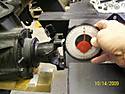
In the picture you can see shims under the axle housing to get it right before I adjusted the four link heim joints.