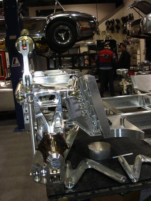
Here is a shot of the right rear suspension. Notice the hollowed out rear upright. That is to allow air to flow through the upright to more effectively cool the brakes. That is a trick we took from F1.
Interestingly, you can also notice 2 "false start" rear upper control arms laying there on the table. One of them is the fault of a customer of ours who came in one day with his new Ferrari 430. We begged him to put it on the lift and when we did...well, we saw a better way. The other is the fault of Cosmos (Finite Element Analysis)...telling us we needed more material.
Also, notice we carefully lined the push rod up on the rocker and shock to minimize any side loading that could occur. Finally, you can also see the lower push rod is also mounted in double shear. That way we can get away with very small bolts and fasteners and make a very strong part.
From this view you can see the rear bulk head is slanted backwards--just like an original car. It made the actual manufacture of the part extremely difficult. There were almost constant battles between engineering and manufacturing on this--engineering always won--and I lost my hair (but unfortunately, not my waist!)

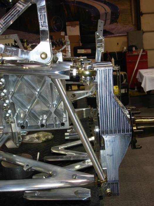
Here is a shot of the right rear suspension corner looking forwards. If you look closely you can see the push rod is actually slightly tapered. A push rod is loaded in compression so its failure mode will be buckling. Buckling almost invariably happens in the middle of the part and so we made the middle of the part thicker. There is no reason to make the ends thick--so we cut them off!
If you look at the leading edge of the rear lower control arm, you can see we milled (right into the billet of the control arm) the mounting brackets for the stainless steel brake flex lines. We wanted to keep them safely out of the way of any flying rocks, bugs, jihadis, politicians, or Corvettes our customer happened to run over. Besides, they look really cool tied up like that. The flex lines on an original Cobra aways bugged me they were just left flapping in the breeze. I didn't want lines flapping in the breeze on my automotive sculpture.
Notice the rear bulk head is completely milled out to reduce weight.
Also, notice the really cool adjuster sleeve nuts on the rear upper control arm. The sleeve nuts are threaded with a right hand thread on the outside (next to the control arm) and they have a left hand thread on the rod end. That way you don't have to take the mounting bolt off of the control arm to adjust camber, caster, or toe! Just loosen the jam nuts (not shown in the picture--we forgot them) and turn the sleeve nut and the wheel will move. Then just tighten the jam nuts back down again. On an original Cobra you have to take the control arm bolts OUT of the car to adjust the caster and then shim the control arm forward or backwards. To adjust the camber on the rear you have to take the bolt out, turn the rod end at least 1/2 a turn, and the assemble everything again. It is a real pain. With this sleeve nut option, we can adjust camber, caster, and toe to 0.001 inch if we want to. We borrowed this idea from a Riley and Scott chassis we saw.
Notice the drive flange is extremely tight to the upright. That is so we could make the 1/2 shafts as long as possible. The longer the 1/2 shaft, the less angularity they 1/2 shaft CV bearings see as the wheel moves up and down. That helps the bearings to last longer. The drive flange is made just like a modern car with a splined axle that goes all the way through the hub. If there is an axle failure (almost impossible with the 17-4 material we are using) then the hub will still be able to rotate on the bearing. If you break an axle on an original Cobra then the wheel will fall off. Now, not to scare anyone here as I haven't seen a wheel fall of in years...the last one was a 289 that was originally under engineered in the first place. But, this is customer I definitely didn't want to see on You Tube.
Also, from this angle you can really see the drive pins are milled directly into the rear hub. No need to worry if you torqued your drive pins here! They will never come loose.
