Welcome to Club Cobra! The World's largest
non biased Shelby Cobra related site!
- » Representation from nearly all
Cobra/Daytona/GT40 manufacturers
- » Help from all over the world for your
questions
- » Build logs for you and all members
- » Blogs
- » Image Gallery
- » Many thousands of members and nearly 1
million posts!
YES! I want to register an account for free right now!
p.s.: For registered members this ad will NOT show
 
 Main Menu
|
 Nevada Classics
|
 Advertise at CC
|
 November 2024
|
| S |
M |
T |
W |
T |
F |
S |
| |
|
|
|
|
1 |
2 |
| 3 |
4 |
5 |
6 |
7 |
8 |
9 |
| 10 |
11 |
12 |
13 |
14 |
15 |
16 |
| 17 |
18 |
19 |
20 |
21 |
22 |
23 |
| 24 |
25 |
26 |
27 |
28 |
29 |
30 |
|
 CC Advertisers
|
|

10-04-2011, 06:27 AM
|
 |
CC Member

|
|
|
Join Date: Jun 2009
Location: Sydney,
NSW
Cobra Make, Engine: RCM, Jag front and rear, LS3
Posts: 1,640
|
|

 Not Ranked
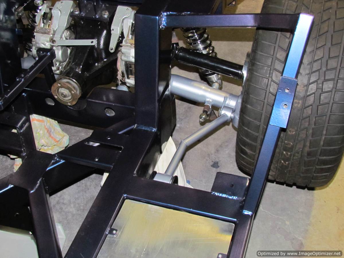
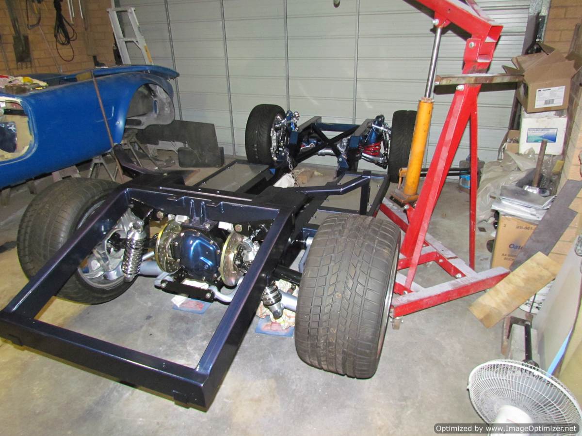
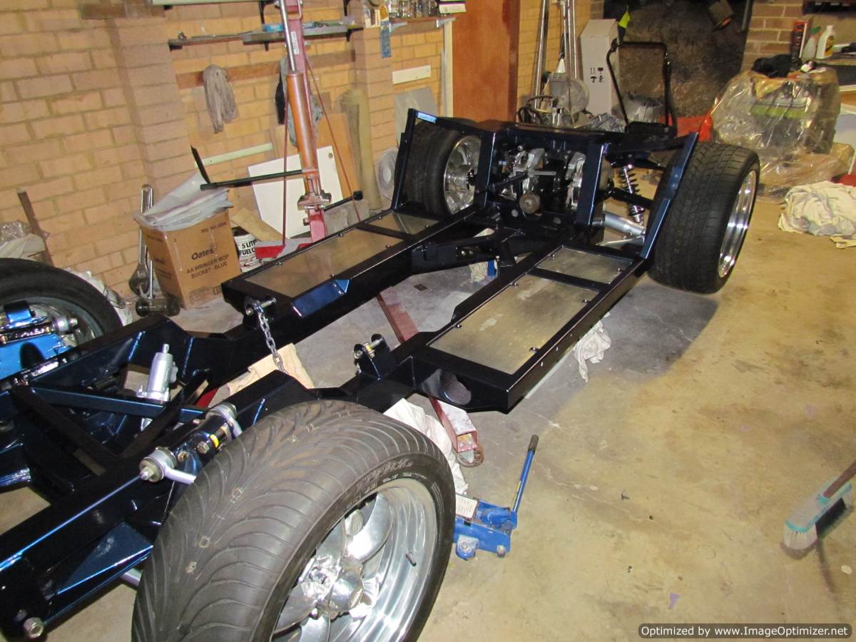
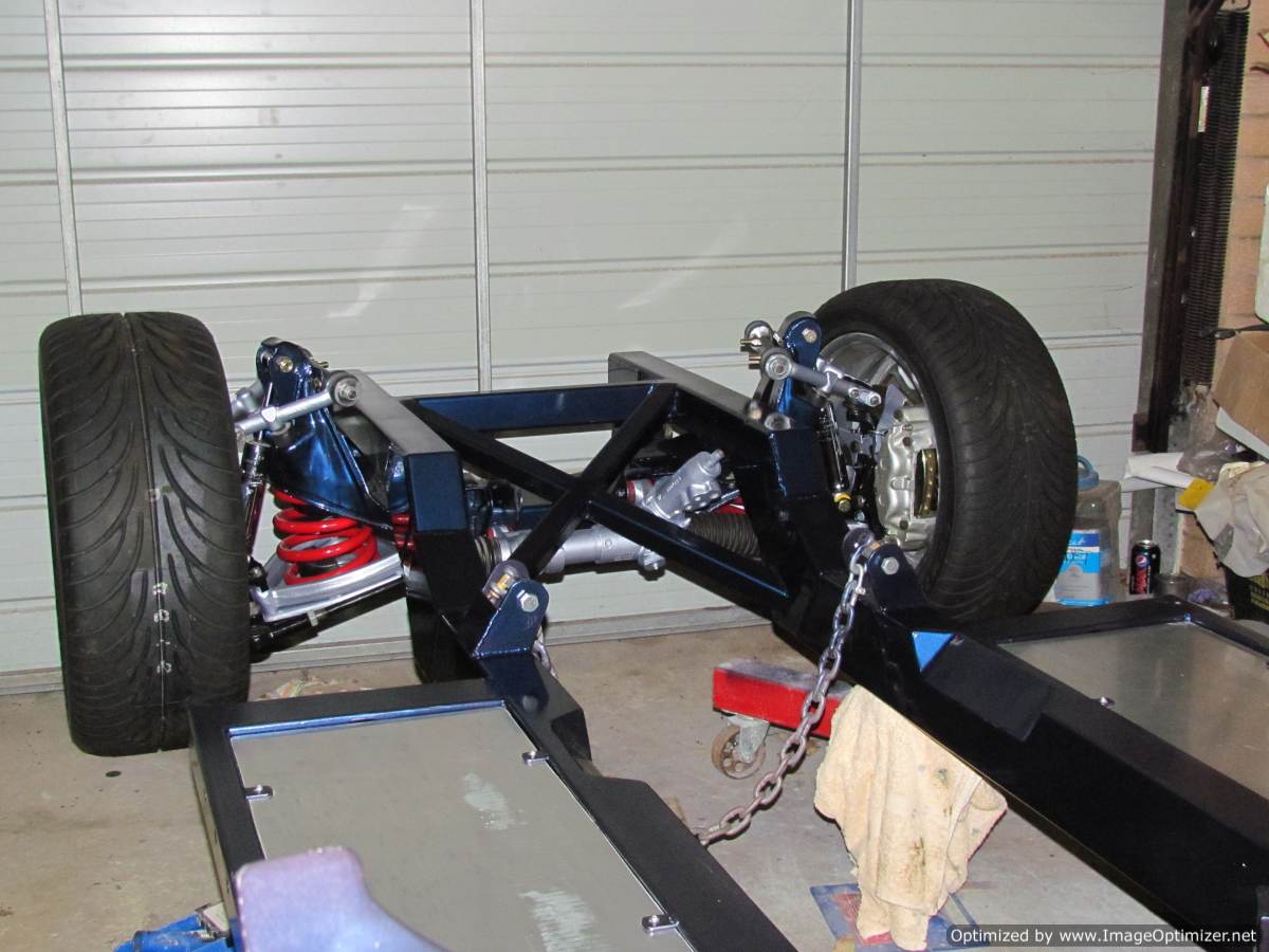
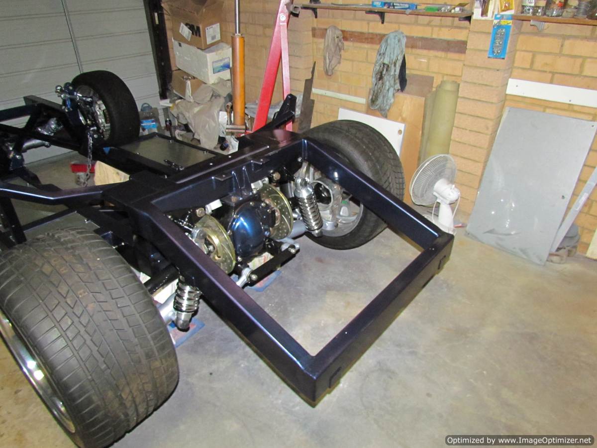
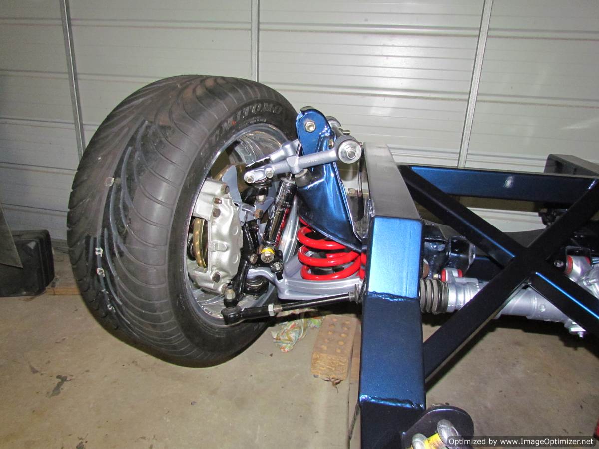
 Some assembly progress pics

|
-
Advertising


10-04-2011, 03:18 PM
|
 |
CC Member

|
|
|
Join Date: Jul 2007
Location: Sydney Australia,
NSW
Cobra Make, Engine: RMC with 6 litre 307KW LS2, Comp Cam, 348rwhp & 532.5 ftlb of torque with 6L80E Tiptronic Transmission
Posts: 1,400
|
|

 Not Ranked
Looking great Liam. Congratulations. It can be done.
Baz
|

10-04-2011, 04:39 PM
|
 |
CC Member

|
|
|
Join Date: Jan 2001
Location: Sunbury,
VIC
Cobra Make, Engine: Rat Rod Racer, LS1 & T56
Posts: 5,391
|
|

 Not Ranked

Looking good Liam,
My only concern is the trailing arm design. It would put quite a lot of twist into the bushing and the arm as the suspension goes through it's travel. It might make the bushing fail prematurely or fatigue the weld. I would make the arms with a spherical bearing or a heim joint on one end to let the end rotate freely whilst maintaining alignment. You would still have some rubber isolation from the chassis with a bush on one end so should be OK for rego. I would also make them from one straight section of tube rather than putting a kink in them. There's plenty of clearance there.
The other thing, with the location of those chassis mounts you are going to get some change in rear toe as the suspension moves up and down. The pivot really needs to be on the center line of the lower inboard control arm mount so you can draw a triangle through the 3 points. The arc the trailing arms currently move through will push the wheel forwards and back through it's travel butting some loads on the lower pivots.
Not a criticism, just an observation.
Cheers
__________________
Mike Murphy
Melbourne Australia
Last edited by Aussie Mike; 10-04-2011 at 04:50 PM..
|

10-04-2011, 04:55 PM
|
 |
CC Member

|
|
|
Join Date: Jan 2001
Location: Sunbury,
VIC
Cobra Make, Engine: Rat Rod Racer, LS1 & T56
Posts: 5,391
|
|

 Not Ranked
You could maybe swap left and right dog bones and run the trailing arms back to the rear of the chassis. That way you could put the mounts on the center line of the inner pivots. This would depend on the design of your fuel tank of course.
Cheers
__________________
Mike Murphy
Melbourne Australia
|

10-04-2011, 08:27 PM
|
 |
CC Member

|
|
|
Join Date: Jun 2009
Location: Sydney,
NSW
Cobra Make, Engine: RCM, Jag front and rear, LS3
Posts: 1,640
|
|

 Not Ranked

Hi Mike,
Thanks for the feedback.
I was concerned about those points also. I spent a lot of time exploring options by looking at other cobras, and also a lot of hot rods. Also drew up a few sketches to calculate the displacement caused by the arc for various trailing arm lengths. The ideal situation is to have long arms that intersect with the axis of the inner fulcrum on the control arm. These virtually have to mount halway down the car next to the gear box (or to the rear of the car). This works on a hot rod but no chance on my chassis without hanging below and limiting ground clearance. Laurie (RCM) said that he used to use the jag arms modified to run on an angle by cutting them and rewelding. I chose not to use the jag arms because i dont like the look of them and i already had the parts to make my own, but apparently that works ok.
I considered Rose joints but thought they wouldnt provide enough movement to compensate for the arc and hence cause toe in. I couldnt run the arms straight cause they would clash with seat mount and exhaust holes in the chassis. I also considered going rearwards except the fuel tank gets in the way and there would also be no room for undercar exhaust.
With the shocks removed i can move the suspension through the full travel without any binding or noticeable drag so i dont think there will be any bump steer issues. Durability of bushes is a concern though. Only time will tell how this goes. If the jag bushes wear out i can replace them with Rose joints quite easily by just cutting and welding in a bung to the tube.
The patrol bush on the front provides a lot of flex as these are used on arms about 2/3 the length of mine and there is double the travel on 4x4 suspension when compared to a cobra. The tube for the rear bush is welded on at a slight vertical angle so as to match the angle of the control arms at ride height.
I think it should be ok. Only time will tell!

|

10-04-2011, 08:45 PM
|
 |
CC Member

|
|
|
Join Date: Aug 2001
Location: Melbourne, Australia,
Vic
Cobra Make, Engine: G-Force Mk I, 5L Windsor, TKO 600, enhanced Jag / Koni suspension & LSD Diff.
Posts: 2,300
|
|

 Not Ranked
Liam
Following Mike's note the G-Force run a long bar forward with the front using a bush but the rear at the suspension a heim joint as Mike suggests.
Obviously setting up the brackets and frames might be an issue on your design.
Also a question on your rear brake attachment bolts, are the nuts you used nylocs or the special binding style you really need to use to avoid the plastic melting in the nylocs under braking?
Obviously if you need to change them now is the time whilst they are very easy to access.
__________________
slowy
|

10-04-2011, 08:52 PM
|
 |
CC Member

|
|
|
Join Date: Aug 2009
Location: Atlanta,
GA
Cobra Make, Engine: 86 Everett Morrison 90" WB. 428 FE
Posts: 1,151
|
|

 Not Ranked
Liam,
I'm curious why you cut and welded the trailing arms? Seems you would lose some rigidity? Plus if the mounts are bushed, it looks like they would bind through travel. I would think a straight link with heims would work better.
Ralphy
__________________
What?
Last edited by Ralphy; 10-04-2011 at 09:13 PM..
|

10-05-2011, 02:47 AM
|
 |
CC Member

|
|
|
Join Date: Jun 2009
Location: Sydney,
NSW
Cobra Make, Engine: RCM, Jag front and rear, LS3
Posts: 1,640
|
|

 Not Ranked
Quote:
Originally Posted by stephen low

Liam
Following Mike's note the G-Force run a long bar forward with the front using a bush but the rear at the suspension a heim joint as Mike suggests.
Obviously setting up the brackets and frames might be an issue on your design.
Also a question on your rear brake attachment bolts, are the nuts you used nylocs or the special binding style you really need to use to avoid the plastic melting in the nylocs under braking?
Obviously if you need to change them now is the time whilst they are very easy to access.
|
Not sure what you mean by brake attachment bolts. Do you mean the nuts that hold the brake disc and half shaft flange? The nuts are a special type of crushed nut that are sort of sqashed at the top to make them lock. |

10-05-2011, 02:58 AM
|
 |
CC Member

|
|
|
Join Date: Jun 2009
Location: Sydney,
NSW
Cobra Make, Engine: RCM, Jag front and rear, LS3
Posts: 1,640
|
|

 Not Ranked
Quote:
Originally Posted by Ralphy

Liam,
I'm curious why you cut and welded the trailing arms? Seems you would lose some rigidity? Plus if the mounts are bushed, it looks like they would bind through travel. I would think a straight link with heims would work better.
Ralphy
|
You cant see it in those photos, but there is a hole throus the chassis for the exhaust to pass through. They are not regular bushes they are trailing arm bushes which allow twist the same as a heim joint.
This is a video i took. i am lifting it with 2 fingers whilst holding the camera with the other hand...no binding!
01102011006.mp4 - YouTube
Last edited by Zedn; 10-05-2011 at 03:04 AM..
|

10-05-2011, 03:32 AM
|
 |
CC Member

|
|
|
Join Date: Aug 2001
Location: Melbourne, Australia,
Vic
Cobra Make, Engine: G-Force Mk I, 5L Windsor, TKO 600, enhanced Jag / Koni suspension & LSD Diff.
Posts: 2,300
|
|

 Not Ranked
Liam
Yes your assumption about what I was getting at is right and you've used the right nuts by your description.
Just looked like nylocs in your picture and I'd have hated to not have mentioned anything had they actually been nylocs in regards to the risk of failure down the track when you do get the beast up and rolling.
Frame looks good and makes me want to go source a replacement diff cover to have it sprayed up in one of the body colours I'll be using. Might be a bit odd though against an all black chassis and not visible anyway.
I'll settle for a running car at this time.
Cheers
Steve
__________________
slowy
|

10-05-2011, 03:45 AM
|
 |
CC Member

|
|
|
Join Date: Jun 2009
Location: Sydney,
NSW
Cobra Make, Engine: RCM, Jag front and rear, LS3
Posts: 1,640
|
|

 Not Ranked

Quote:
Originally Posted by stephen low

Liam
Yes your assumption about what I was getting at is right and you've used the right nuts by your description.
Just looked like nylocs in your picture and I'd have hated to not have mentioned anything had they actually been nylocs in regards to the risk of failure down the track when you do get the beast up and rolling.
Frame looks good and makes me want to go source a replacement diff cover to have it sprayed up in one of the body colours I'll be using. Might be a bit odd though against an all black chassis and not visible anyway.
I'll settle for a running car at this time.
Cheers
Steve
|
Yes, i went to my bolt shop and told them i needed lock nuts that could handle high heat. That is what they ordered in for me. I also replaced the bolts with new ones to be on the safe side. The other bolts on the rear end have been tied with safety wire and locktite'd as well.
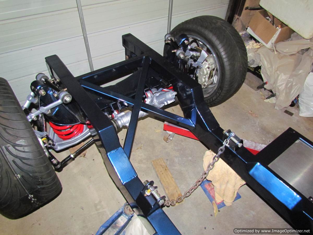
I have gone a bit trigger happy with the spray gun as you can see. I know it wont be seen but i couldnt resist. Will probably end up having to strip it all down and do it in black after a couple of years, but its fun for now.

|

10-05-2011, 03:52 AM
|
|
CC Member

|
|
|
Join Date: May 2002
Location: Brisbane Australia,
QLD
Cobra Make, Engine: RMC under re-construction, GenIV with tremec 600, Jag 3.31 L/S diff
Posts: 3,318
|
|

 Not Ranked
Liam, I've gotta agree with the others.
I've looked at your vid and whilst the lower arm seems to move smoothly without bind it is a whole different ball game when aggressively accelerating or braking.
My RMC (like the G-Force) has a longish straight trailing arm which seems to work ok with an adjustable heim at one end if adjusted properly. But I'm not overly in favor of it.
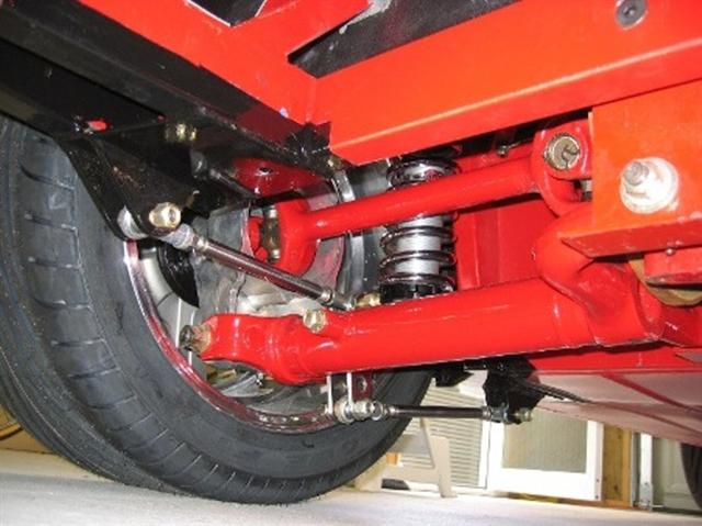
For what it's worth the following pic shows the only system I feel works adequately to relieve the forces on a Jag lower arm in our cobras.
__________________
It's impossible to soar like an eagle when you're surrounded by turkeys.
|

10-05-2011, 07:47 AM
|
 |
CC Member

|
|
|
Join Date: Jan 2001
Location: Sunbury,
VIC
Cobra Make, Engine: Rat Rod Racer, LS1 & T56
Posts: 5,391
|
|

 Not Ranked
I was going to suggest a Watts linkage setup but I'd only seen them with an attachment to the top of the Jag upright. That's a neat setup in your pic there Les. It could be set up as a bolt on to Liam's existing chassis.
Cheers
__________________
Mike Murphy
Melbourne Australia
|

10-05-2011, 08:37 AM
|
|
CC Member

|
|
|
Join Date: May 2002
Location: Brisbane Australia,
QLD
Cobra Make, Engine: RMC under re-construction, GenIV with tremec 600, Jag 3.31 L/S diff
Posts: 3,318
|
|

 Not Ranked
Mike, I really don't like the watts linkage set to the top of the Jag upright. Being fitted to the top of the upright I feel it doesn't really prevent movement of the lower arm.
That watts link in the pic is on a DRB and if set up properly, it wont bind for the full travel of the suspension.
The owner used to hang in here on CC but I've not seen him for a while..
The other nice thing of that link is that because the load is taken between two arms, one in tension and one in compression then the components can be somewhat less bulky than a single arm.
__________________
It's impossible to soar like an eagle when you're surrounded by turkeys.
|

10-05-2011, 10:40 PM
|
|
CC Member

|
|
|
Join Date: Jul 2003
Cobra Make, Engine: Unique Motorcars 289 USRRC, 1964 289 stroked to 331, toploader
Posts: 1,086
|
|

 Not Ranked

Quote:
Originally Posted by Rebel1

I really don't like the watts linkage set to the top of the Jag upright. Being fitted to the top of the upright I feel it doesn't really prevent movement of the lower arm.
That watts link in the pic is on a DRB and if set up properly, it wont bind for the full travel of the suspension.
The owner used to hang in here on CC but I've not seen him for a while..
The other nice thing of that link is that because the load is taken between two arms, one in tension and one in compression then the components can be somewhat less bulky than a single arm.
|
Good call! The Watts link at the top of the hub carrier is for stopping torsion of the lower control arm (LCA) under load, not for fore-aft stabilization of the LCA. I, too, like the way this guy set up the Watts link on the LCA... and I am considering something like this for mine  .
__________________
Paul
Unique Motorcars 289 USRRC
1964 289 5-bolt block
Toploader and 3.31 rear
|

10-06-2011, 01:58 AM
|
 |
CC Member

|
|
|
Join Date: Aug 2001
Location: Melbourne, Australia,
Vic
Cobra Make, Engine: G-Force Mk I, 5L Windsor, TKO 600, enhanced Jag / Koni suspension & LSD Diff.
Posts: 2,300
|
|

 Not Ranked
 G-Force trailing arm comparison
Liam
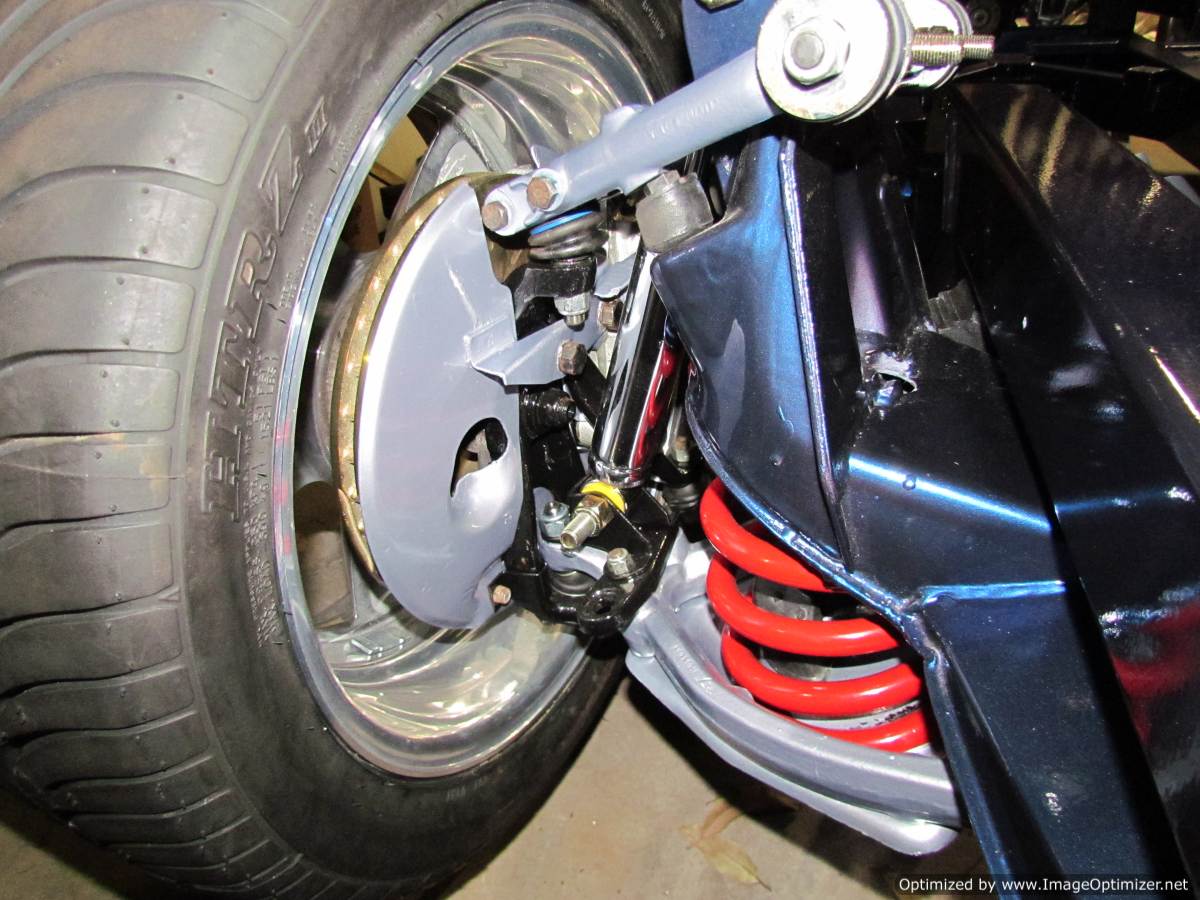
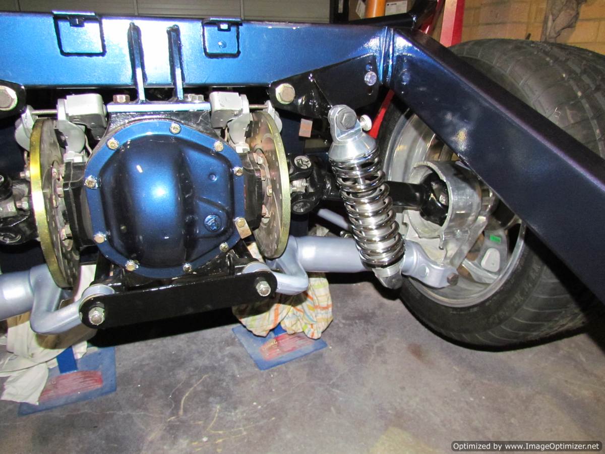
Took me a while to find suitable pictures but here is the G-Force version for your information.
The connection from arm to chassis using a heim joint

And bushed attachment to the lower arms

Guessing you're too far down the track for change but it doesn't hurt to see how other kits manage the same idea.
Plus I have some understanding of the geometry planning needed here but no experience and I can only hope GF have it right. Other GF owners are not complaining so it can't be too far wrong.
Good luck anyway.
Steve
__________________
slowy
|

10-06-2011, 07:56 AM
|
 |
CC Member

|
|
|
Join Date: Aug 2009
Location: Atlanta,
GA
Cobra Make, Engine: 86 Everett Morrison 90" WB. 428 FE
Posts: 1,151
|
|

 Not Ranked
Please tell me if I am wrong. The forward link you have arrests the wishbone from moving forward during acceleration. This induces a rotational twist in the wishbone (a lever), looking from the drivers side the wishbone would be stressed in a clockwise direction. If you added an upper link the force on it (the upper link) would be toward the rear of the chassis. Not having an upper link allows this twisting to go on. So, having your coilover to the rear adds even more torque (twist) on the wishbone, putting the weight on the back. Your coilover would serve a better purpose being toward the front of the halfshaft, counter reacting under acceleration. Also, when a chassis flexes the further back you put the coilover. The amount (distance) of travel is greater when flexing. So again the coilover serves better to be forward. Am I wrong?
__________________
What?
|

10-06-2011, 02:01 PM
|
 |
CC Member

|
|
|
Join Date: Jun 2009
Location: Sydney,
NSW
Cobra Make, Engine: RCM, Jag front and rear, LS3
Posts: 1,640
|
|

 Not Ranked

Quote:
Originally Posted by Ralphy

Please tell me if I am wrong. The forward link you have arrests the wishbone from moving forward during acceleration. This induces a rotational twist in the wishbone (a lever), looking from the drivers side the wishbone would be stressed in a clockwise direction. If you added an upper link the force on it (the upper link) would be toward the rear of the chassis. Not having an upper link allows this twisting to go on. So, having your coilover to the rear adds even more torque (twist) on the wishbone, putting the weight on the back. Your coilover would serve a better purpose being toward the front of the halfshaft, counter reacting under acceleration. Also, when a chassis flexes the further back you put the coilover. The amount (distance) of travel is greater when flexing. So again the coilover serves better to be forward. Am I wrong?
|
Hi Ralphy,
The flex will occur at sudden acceleration or braking so it goes both ways. That being said we are talking about a 5mm wall pipe that is not very long and in my case it is sleaved with another 5mm pipe. There are 2 areas on the Jag rear that spark a lot discussion. One is the trailing arms and the other is as you have raised, the shocks.
I will be running shocks on both sides as they are in the jag. In other words there will be 4 shocks when finished.
Liam

|

10-06-2011, 03:51 PM
|
 |
CC Member

|
|
|
Join Date: Sep 2004
Location: Canberra,
ACT
Cobra Make, Engine: G-Force Cobra '68 302, T-5, Jag 3.77 LSD.
Posts: 993
|
|

 Not Ranked

I wouldn't think there is an issue of strength in the lower dog bone, but the weaker point being the inner pivot bracket and bolts. I'm not sure how much strength the original trailing arm actually contributes, as the original Jag forward mount is a large and very compliant rubber bush. I rekon it's only there to stop you loosing the the dog bone and your wheel when it gets ripped off by a QLD pot hole. A bit like a leg rope 
I have a G-Force and it is like Slowy's - it essentially turns the dog bone into a wishbone, putting it in compression under acceleration, but as you can see on Zden's chassis it is not possible to do this as a chassis member is obsucting it.
The single shock set up on the red chassis is mounted forward of the arm, and i have been considering going that way with mine.
I really like the adjustable shock mounts on the RCM. I mighty try and retrofit to mine. My spring rates are just right but they are set at the lowest height on the spring seats and it is still to high in the rear.
__________________
SLIPRY
|

10-06-2011, 04:46 PM
|
 |
CC Member

|
|
|
Join Date: Aug 2009
Location: Atlanta,
GA
Cobra Make, Engine: 86 Everett Morrison 90" WB. 428 FE
Posts: 1,151
|
|

 Not Ranked
Liam forces do go both ways, however considering rear brakes at best offer 25% of your braking force vs. acceleration at 100% rear. Plus the rear unloading during braking there is no comparison. I also wondered if you were to add front coilovers. In your pics I see no upper mount.
__________________
What?
|
 Posting Rules
|
You may not post new threads
You may not post replies
You may not post attachments
You may not edit your posts
HTML code is Off
|
|
|
All times are GMT -7. The time now is 05:15 AM.
|
|

















 .
.


 Linear Mode


