Welcome to Club Cobra! The World's largest
non biased Shelby Cobra related site!
- » Representation from nearly all
Cobra/Daytona/GT40 manufacturers
- » Help from all over the world for your
questions
- » Build logs for you and all members
- » Blogs
- » Image Gallery
- » Many thousands of members and nearly 1
million posts!
YES! I want to register an account for free right now!
p.s.: For registered members this ad will NOT show
 
 Main Menu
|
 Nevada Classics
|
 Advertise at CC
|
 November 2024
|
| S |
M |
T |
W |
T |
F |
S |
| |
|
|
|
|
1 |
2 |
| 3 |
4 |
5 |
6 |
7 |
8 |
9 |
| 10 |
11 |
12 |
13 |
14 |
15 |
16 |
| 17 |
18 |
19 |
20 |
21 |
22 |
23 |
| 24 |
25 |
26 |
27 |
28 |
29 |
30 |
|
 CC Advertisers
|
|
 35Likes 35Likes

04-12-2018, 05:29 AM
|
 |
CC Member

|
|
|
Join Date: Apr 2008
Location: Melbourne,
VIC
Cobra Make, Engine: Classic Revival CR 3505, LS1, T56 6 Speed, VE 3.45 LSD Rear, 6 Spot AP Fronts, 4 Spot Wilwood Rears
Posts: 1,121
|
|

 Not Ranked
 Broken A-Arm
Hi Everyone,
Recently during some track time at Phillip Island with the CCCV I noticed my car would "move around a bit" especially at high speed on the straights 
It was a very gusty day and I put it down to that. Did a quick check in the pits and everything seemed ok.
But when I finished the day the steering felt a bit spongy.
Upon a detailed inspection when I got home I found I had a broken passenger side A-Arm. I think it might have been cracked or fractured prior to the event - I had done my pre-race check and didnt pick it up. So not sure.
I contacted Dan at Classic Revival and he made me two new A-Arms and installed new bushes and lower ball joint. All in a relatively short time. Thanks Dan for great service.
Installed them both tonight and did a quick front end alignment check - need to adjust by 2mm, road test and all good.
I reckon those potholes on Melb roads were the cause of this, I've done 30,000Klms over 10 years.
Anyway, here's some pics. Heading off to Winton next week weather permitting for a test day, should be fun.
cheers
Gregg
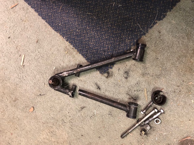

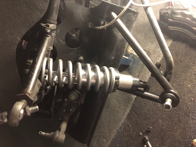 |
-
Advertising


04-12-2018, 06:10 AM
|
 |
CC Member

|
|
|
Join Date: Mar 2004
Location: Warwick,
Qld
Cobra Make, Engine: DRB, FORD 302W,T5
Posts: 487
|
|

 Not Ranked
Lucky eh!
That's why I hate fabricated A arms -- cause you'll never know the skill level of the fabricator or the materials used -- unless they come with an engineering certification
|

04-12-2018, 07:08 AM
|
|
CC Member

|
|
|
Join Date: Jun 2006
Location: Newcastle, Warners Bay,
NSW
Cobra Make, Engine: RMC . 393 Dart alloy block Stroked 351 alloy heads ..all the goodies plus a pre oiler. al
Posts: 1,495
|
|

 Not Ranked
Yep all my stuff is in a light colour so that cracks, oil leaks etc can be seen easier. Black hides too much. It's a NASCAR trick. |

04-12-2018, 02:11 PM
|
|
CC Member

|
|
|
Join Date: Apr 2011
Location: Orange,
NSW
Cobra Make, Engine: Dax
Posts: 429
|
|

 Not Ranked
That’s got nothing to do with quality of steel / fabrication and everything to do with the design of the A-arm and where the forces go. Failures like this are typical for a-arms where the shock is part way up the arm like that with a resulting bending moment. Designing for shock loads from potholes is easy and has been done for years (VSB 14 quotes similar numbers to those used by Lotus in the 1950’s for road cars... a bump is a bump is a bump).
A better solution is to change the force paths in the arm.
Treeve
|

04-12-2018, 04:37 PM
|
 |
CC Member

|
|
|
Join Date: Apr 2008
Location: Melbourne,
VIC
Cobra Make, Engine: Classic Revival CR 3505, LS1, T56 6 Speed, VE 3.45 LSD Rear, 6 Spot AP Fronts, 4 Spot Wilwood Rears
Posts: 1,121
|
|

 Not Ranked
I see what you mean. Not sure though if you could get the lower shocker mount any closer as its already nearly 45 degree angle and it would interfere with the tyre/wheel etc I think. But then I know nothing about this subject. cheers Gregg
|

04-12-2018, 04:45 PM
|
|
CC Member

|
|
|
Join Date: Apr 2011
Location: Orange,
NSW
Cobra Make, Engine: Dax
Posts: 429
|
|

 Not Ranked
And that’s where an engineer comes in with alternatives like push rod suspension, changing the design to be better suited to the loads being carried, changes to the type of shock mounting, changes to the mounting location on the arm (looks like the welds are in tension over bumps which isn’t a great choice.
Definitely a raft of available improvements if engineered correctly. And engineering is very different to fabrication in this sense.
Treeve
|

04-12-2018, 08:08 PM
|
 |
CC Member

|
|
|
Join Date: May 2008
Location: Brisbane,
QLD
Cobra Make, Engine:
Posts: 2,797
|
|

 Not Ranked
Quote:
Originally Posted by Treeve

And that’s where an engineer comes in with alternatives like push rod suspension, changing the design to be better suited to the loads being carried, changes to the type of shock mounting, changes to the mounting location on the arm (looks like the welds are in tension over bumps which isn’t a great choice.
Definitely a raft of available improvements if engineered correctly. And engineering is very different to fabrication in this sense.
Treeve
|
Yes, the welds are under tension, and waiting for failure.
The tube has fractured at the highest stress point, and the weakest after the welding process.
Tubes need to be thicker wall and/or larger diameter.
Gary
Last edited by Gaz64; 04-13-2018 at 02:19 AM..
|

04-12-2018, 10:58 PM
|
|
CC Member

|
|
|
Join Date: Apr 2011
Location: Orange,
NSW
Cobra Make, Engine: Dax
Posts: 429
|
|

 Not Ranked
So, move the tubes and redesign the connection. Making everything thicker and heavier is a cop-out. Putting the a-arm together then drilling for the suspension mount tube through the side will reduce this, and then reinforcing plates can be added. Alternatively , running some numbers on appropriately sized gussets and designs can help to ensure there is no significant change in modulus through the arm and hence eliminate the sudden change. Finally, you could go back to scratch and consider changing the top mount so you can move the bottom mount. This then changes the force paths and hence you could redesign it to be stronger and lighter.
Treeve ‘not my first rodeo’ the engineer
|

04-13-2018, 05:07 AM
|
 |
CC Member

|
|
|
Join Date: Apr 2006
Location: Mildura,
vic
Cobra Make, Engine: FFR Coupe, 416ci of LS goodness
Posts: 2,349
|
|

 Not Ranked
C’mon Treeve,
Those arms were designed by an engineer!
__________________
Powered by Cu
|

04-13-2018, 03:02 PM
|
|
CC Member

|
|
|
Join Date: Apr 2011
Location: Orange,
NSW
Cobra Make, Engine: Dax
Posts: 429
|
|

 Not Ranked
Iíve made ****ty design choices in the past too - and Iím sure Iíll make them in the future. But not in an area that I have a fair bit of experience in.
My point is - these will probably work just as well as the exact previous ones did. And they broke. So why do the same thing and expect a different outcome?
My aim was to highlight some opportunities for improvement that wouldnít be too hard to implement.
Last edited by Treeve; 04-13-2018 at 03:04 PM..
|

04-13-2018, 03:28 PM
|
 |
CC Member

|
|
|
Join Date: Feb 2006
Location: Gilroy,
CA
Cobra Make, Engine: SPF 2291, Whipple Blown & Injected 4V ModMotor
Posts: 2,719
|
|

 Not Ranked
In the FWIW category all the stress in that assembly is located between the shock mount and the ball joint. The trailing portion of the arm that actually broke, goes to the frame pivot and carries next to no stress compared to the portion between the ball joint and the shock mount.
I think the real problem here is a lack of government control! We need legislation passed that requires weldments and their various components to be a non stressed portion of the suspension system, a full background check should be required before the sale of any welding rod and certainly registration (or is that castration —  ) of all welded suspension components would go a long way to eliminating this type of problem. Seems like something ought to be castrated though ...
Sadly, it appears that we have been let down, yet again, by our fine elected representatives  — simply the best that money can buy!
Ed
__________________
 Help them do what they would have done if they had known what they could do.
|

04-13-2018, 07:54 PM
|
|
CC Member

|
|
|
Join Date: Apr 2011
Location: Orange,
NSW
Cobra Make, Engine: Dax
Posts: 429
|
|

 Not Ranked
In the FWIW category on this, the bending moment is created in relation to the the two areas that you suggest with the shock acting as a simple support for the wheel to impose the moment around. The weld failed in the heat affected zone and hence is exactly where a failure would be expected if it were not a cracked weld in and of itself. So the failure has a lot to do with design. And the American system is a lot more free than the Australian system.
Last edited by Treeve; 04-14-2018 at 03:52 PM..
|

04-13-2018, 11:28 PM
|
 |
CC Member

|
|
|
Join Date: Apr 2006
Location: Mildura,
vic
Cobra Make, Engine: FFR Coupe, 416ci of LS goodness
Posts: 2,349
|
|

 Not Ranked
Quote:
Originally Posted by cycleguy55

|
Brian, you need to brush up on your sarcasm skills.
__________________
Powered by Cu
|

04-13-2018, 11:29 PM
|
 |
CC Member

|
|
|
Join Date: Feb 2006
Location: Gilroy,
CA
Cobra Make, Engine: SPF 2291, Whipple Blown & Injected 4V ModMotor
Posts: 2,719
|
|

 Not Ranked
This failure has to do with a faulty weld or possibly a damaged portion of tubing. In order to determine the actual reason for failure an examination of the failed component would be required. The failure most probably does not have to do with vehicle weight imposed loading. Almost (but not all) all of that load is absorbed by the tubing between the shock and the ball joint.
A bad weld is not a bad design, it is a bad weld. While we are in the FWIW mode, bending moments are not created by areas they are created by forces. Units of force are quite different than units of area, do not describe the same physical phenomena and in fact are not interchangeable.
Ed
__________________
 Help them do what they would have done if they had known what they could do.
|

04-14-2018, 02:30 AM
|
 |
CC Member

|
|
|
Join Date: Jun 2000
Location: Cape Town, South Africa/Mainz, Germany,
Posts: 1,601
|
|

 Not Ranked
What do you think about the failure having resulted from the twisting motion when you brake? I would be more happy if this A-arm had a gusset/tube on the wide side, across the two tubes. Making it a better "A".
__________________
If I don't respond anymore, that's because I can't log in
Last edited by Dominik; 04-14-2018 at 03:02 AM..
Reason: typo
|

04-14-2018, 04:36 AM
|
|
CC Member

|
|
|
Join Date: Apr 2011
Location: Orange,
NSW
Cobra Make, Engine: Dax
Posts: 429
|
|

 Not Ranked
Fair point Ed you win. Good to see you offered some constructive design alternatives and helped improve it. I also note your ability to talk to the ‘everyman’ as well as using long words in ways they’ll understand. Your description of how the loads will be absorbed is utter bollocks, and I’m struggling to understand what other forces are in a vehicle which don’t involve it’s weight from undriven wheels. Your condescenion and pedanticism is expected - but please make sure if you’re going to sling **** about how imperfect someone’s post is - make sure your own back yard is perfect first. From your last post you might want to practice what you preach.
Treeve
Last edited by Treeve; 04-14-2018 at 04:41 AM..
|

04-14-2018, 05:22 AM
|
|
CC Member

|
|
|
Join Date: Sep 2010
Location: Beerwah,
QLD
Cobra Make, Engine:
Posts: 218
|
|

 Not Ranked

Quote:
Originally Posted by Treeve

So, move the tubes and redesign the connection. Making everything thicker and heavier is a cop-out. Putting the a-arm together then drilling for the suspension mount tube through the side will reduce this, and then reinforcing plates can be added. Alternatively , running some numbers on appropriately sized gussets and designs can help to ensure there is no significant change in modulus through the arm and hence eliminate the sudden change. Finally, you could go back to scratch and consider changing the top mount so you can move the bottom mount. This then changes the force paths and hence you could redesign it to be stronger and lighter.
Treeve ‘not my first rodeo’ the engineer
|
Spot on Treeve !!....We have all seen too many fabricated A arms of that nature, on all sorts of "Projects" - A simplistic solution that indicates lack of any engineering consideration, in so many ways. Would not be happy with something like this on my car !! Gregg.....It would not be too difficult to fabricate arms to do the job properly.
Last edited by muzzza; 04-14-2018 at 05:26 AM..
|

04-14-2018, 05:31 AM
|
 |
CC Member

|
|
|
Join Date: May 2008
Location: Brisbane,
QLD
Cobra Make, Engine:
Posts: 2,797
|
|

 Not Ranked
Any failure like that does not deserve to be replaced with the same component.
Find another source.
That is a safety issue, for you, and other road users, and others here will agree.
Gary
|

04-14-2018, 10:53 AM
|
 |
CC Member

|
|
|
Join Date: Feb 2006
Location: Gilroy,
CA
Cobra Make, Engine: SPF 2291, Whipple Blown & Injected 4V ModMotor
Posts: 2,719
|
|

 Neutral

Quote:
Originally Posted by Treeve

Fair point Ed you win. Good to see you offered some constructive design alternatives and helped improve it. I also note your ability to talk to the ‘everyman’ as well as using long words in ways they’ll understand. Your description of how the loads will be absorbed is utter bollocks, and I’m struggling to understand what other forces are in a vehicle which don’t involve it’s weight from undriven wheels. Your condescenion and pedanticism is expected - but please make sure if you’re going to sling **** about how imperfect someone’s post is - make sure your own back yard is perfect first. From your last post you might want to practice what you preach.
Treeve
|
Treeve, it is clear you and I are for the most part not going to find significant agreement. That said my issue is the internet has been and continues to be a conduit that uses its capacity to misinform and spread misinformation. Individuals who know better should not knowingly enhance that capacity to misinform. As an engineer your attention to the correct explanation and underlying detail should be greater than that of the non-engineer.
Your writing and description of the physical phenomena at work here is minimally misleading and your use of terminology to describe the physical phenomena is simply wrong (i.e. forces and areas). Had you not been trained in the discipline(s) you are employing to explain this component failure phenomena then the oversight(s) could be easily excused/overlooked — but you are a degreed engineer (I believe).
Trying to help those without the benefit of the same engineering skills and training is commendable. Doing it in a sloppy fashion that can be misleading or misinterpreted because of it's lack of precision is inexcusable — especially from someone who has been trained otherwise.
The concepts behind most physical phenomena can be explained correctly and understandably without the rigorous precision required to make the engineering calculations of suitability. To eschew that for a misleading representation when you are capable of so much more is in poor form, especially for a degreed engineer.
Ed
__________________
 Help them do what they would have done if they had known what they could do.
Last edited by eschaider; 04-14-2018 at 01:16 PM..
Reason: Spelling & Grammar
|
 Posting Rules
|
You may not post new threads
You may not post replies
You may not post attachments
You may not edit your posts
HTML code is Off
|
|
|
All times are GMT -7. The time now is 08:08 PM.
|
|










 35Likes


 ) of all welded suspension components would go a long way to eliminating this type of problem. Seems like something ought to be castrated though ...
 — simply the best that money can buy!
 Linear Mode


