Club Cobra GasN Exhaust  

Go Back   Club Cobra > Manufacturers, Engine Builders, tools, and parts. > ERA---Speak with Bob Putnam

Keith Craft Racing
Nevada Classics
Keith Craft Racing
Main Menu
Module Jump:
Nevada Classics
Nevada Classics
MMG Superformance
Keith Craft Racing
Advertise at CC
Banner Ad Rates
Keith Craft Racing
MMG Superformance
November 2024
S M T W T F S
          1 2
3 4 5 6 7 8 9
10 11 12 13 14 15 16
17 18 19 20 21 22 23
24 25 26 27 28 29 30

Kirkham Motorsports

Reply
 
LinkBack Thread Tools Display Modes
  #1 (permalink)  
Old 05-07-2013, 01:12 PM
CC Member
Visit my Photo Gallery

 
Join Date: Sep 2012
Location: Portland, OR
Cobra Make, Engine: ERA - B2Motorsports Dart 331
Posts: 464
Not Ranked     
Default Front Pivot Points

I purchased poly for the pivots on the front of my car. When we started to take it apart, I was a little surprised to find the front suspension would not freely articulate with the shocks removed. The spindle and rotor weigh 35lb and I had to force it into the bump limit. Released, it would not drop further than half way and this was after letting it sit all night. I assumed it was because of the use of rubber in the joints.

We installed the poly bushings in the lower arms only, torqued the bolts to spec, and the arms were bound such that they would not drop with a 16 lb weight on the arm. After just a few cycles one the the bushing flanges was severely deformed and had been cut thru - hmm.

I ordered a new set of bushings and we went to work on what was causing the binding. The first thing we did was to pull the bushings and cut the flanges off of them. We reinstalled them into the the control arm tubes and reinstalled the arms.


By cutting the flanges we could measure the gaps between the bushing tubes and the pivot mounts. With the flanges removed I rotated the lower arms and noticed the tube ends were not vertically parallel to the pivot mounts. I had the faces squared on a mill and we reinstalled. Things rotated squarely and freely until we torqued them - still way too tight.

I found specs from the bushing manufacturer that stated the control arm bushing tubes need to be 1.480 long. The tubes on the arms measured 1.520. I had the tubes milled down to 1.490 and we reinstalled. Still the arms would not allow 13lb to drop.

We ordered a piece of 5/8 drill rod and slid it thru the pivot mounts and neither side would accept the rod.


I was a little startled by this at first because I was not sure where datum was. The good thing is the rod contacted at different points on the back pivot mounts. We grabbed a tape and the rods were both parallel to each other and parallel to the ground so we went with the front cross member being datum. We used a die grinder and opened the holes in the rear pivot points to allow the rod to slide thru. We welded in new locating washers on the rear pivot mounts. The rod now cleanly slid thru the pivot mounts.

We ordered another rod and checked the alignment of the control arm tubes and it became apparent why the ends were not parallel to the pivot mounts. The rod would not pass thru the arm tubes - hmm.

We cut three sides of the weld that attaches the tube to the arm, heated the remaining weld with a torch, and rotated the tubes parallel to the welding table until the rod would pass thru the tubes, then welded it all back together. We put the arms back on the mill and took the tube lengths down to 1.480 assuring the ends were parallel and vertical.

I have always liked Prothane bushings because they mold grease grooves in to the I.D. of the bushing. Prothane does not publish any dimensional data on their bushings so I went with Energy Suspension. To achieve the same thing, we milled 6 shallow longitudinal grooves into the bushing sleeves. We installed zircs in the top of the tubes. Side note - the bushing sleeves supplied with the bushings fit the pockets nearly perfect - no more than .020 clearance.

We put it all back together and it will barely hold a 6lb weight. Once it begins to drop, it is straight thru. There is an ever slight amount of static friction I believe between the bushing flanges and the pivot mounts, but it is nothing in the big picture and most likely will wear in.

We are replacing the top arms with some adjustables from Specialty Products
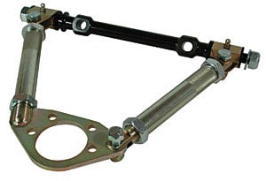


They come with hard bushings, zircs, and swing very freely.

We reassembled with just spindle and the assembly lifts very easily and falls very quickly.

Last edited by ERA2076; 05-09-2013 at 11:00 PM.. Reason: Corrected Picture of Arm
Reply With Quote
  #2 (permalink)  
Old 05-07-2013, 06:18 PM
CC Member
Visit my Photo Gallery

 
Join Date: Dec 2011
Location: York Co. Maine USA, ME
Cobra Make, Engine: ERA 427 S/C W/Holmon Moody Original Nascar build #508 Iron Block/heads (C5AE-H) Bal/Blu 427 Sideoiler; 780 Holley Dbl. Pump; 4 Speed Top Loader; AP Racing Bks; IRS; 15" Trigo pins
Posts: 391
Not Ranked     
Default

Nice work!
Reply With Quote
  #3 (permalink)  
Old 05-07-2013, 09:19 PM
CC Member
Visit my Photo Gallery

 
Join Date: Sep 2012
Location: Portland, OR
Cobra Make, Engine: ERA - B2Motorsports Dart 331
Posts: 464
Not Ranked     
Default

Thanks - anxious to try it, but that is months away
Reply With Quote
  #4 (permalink)  
Old 05-09-2013, 01:08 PM
Fullchat289's Avatar
CC Member
Visit my Photo Gallery

 
Join Date: Mar 2003
Location: McConnellsburg, PA
Cobra Make, Engine: ERA FIA #2124
Posts: 687
Not Ranked     
Default

Interested in seeing what camber/caster numbers you settle on with the adjustable UCA's. Can you give us a p/n and source for these? I know I've seen them in the Speedway Motors catalogue, but where did you get yours?

Thanks,

Allen.
Reply With Quote
  #5 (permalink)  
Old 05-09-2013, 04:50 PM
CC Member
Visit my Photo Gallery

 
Join Date: Nov 2003
Location: New Britain, CT
Cobra Make, Engine: Size 10 Feet
Posts: 3,011
Not Ranked     
Default

Do they sell a ball joint with a taper that matches the Camaro upper that we use? Is there enough angular freedom so that there's no bind in jounce or rebound?
Reply With Quote
  #6 (permalink)  
Old 05-09-2013, 10:57 PM
CC Member
Visit my Photo Gallery

 
Join Date: Sep 2012
Location: Portland, OR
Cobra Make, Engine: ERA - B2Motorsports Dart 331
Posts: 464
Not Ranked     
Default

The image I originally posted is incorrect - please forgive me - I re-posted the image above and a link below to the product. I purchased the arms from Jegs. There are two sizes. I tried the smaller - no good. They are not to be run with more than one inch of exposed thread beyond the jam nuts. We could not achieve this with the shorter arms.

Specialty Products 92556 SPC Race Style Adjustable Upper Control Arms

We have it all bolted together just to align to the spindle and get the thing back on its wheels. On the rack everything cycles very smoothly, with no binding, from full bump to full droop and we have not had to modify the aluminum panels.

That said none of it is set to spec, everything is prototype, but it all looks very promising. We had to move our machine shop so we had to pull off, but hope to be going again next week.

We want to try to run the cross shaft directly against the upright - we have not studied that geometry yet with respect to maintaining the original timing.

Bob, if you can give me any insight here it will be appreciated. Specifically - if we pull the alignment shims and mount straight to the upright, will we affect the timing such that it could not be adjusted in the arms provided the arms have enough adjustment? It is the location of the upper pivot with respect to the lower I am concerned about.

The SPC cross shafts are not offset so we will have moved the pivot point inboard by the amount of the original cross shaft offset + the thickness of the alignment shims. I just don't quite have my mind around this yet.

If the proper timing cannot be achieved, we will either run nominal block spacers behind the cross shaft or use the original Moog cross shafts or a combination of both and then fine tune with the arms.

I purchased Howe low friction ball joints (upper and lower) and some Energy Suspension dust caps. I supplied Howe with the the part numbers specified in the build manual and they sent me the joints.

Howe Racing Enterprises

I have a caster camber gage that threads onto the spindle so that is how we will set it up. Ordered the Penske's yesterday.

Is it all going to work? - I have no idea, but we are entertained and I am very excited to try it out - it operates very, very, smoothly?

Bob - you guy's built the coolest thing ever - it is a joy to work on - thank you.

chr
Reply With Quote
  #7 (permalink)  
Old 05-10-2013, 09:31 AM
CC Member
Visit my Photo Gallery

 
Join Date: Nov 2003
Location: New Britain, CT
Cobra Make, Engine: Size 10 Feet
Posts: 3,011
Not Ranked     
Default

Quote:
Originally Posted by ERA2076 View Post
We want to try to run the cross shaft directly against the upright - we have not studied that geometry yet with respect to maintaining the original timing.

Bob, if you can give me any insight here it will be appreciated. Specifically - if we pull the alignment shims and mount straight to the upright, will we affect the timing such that it could not be adjusted in the arms provided the arms have enough adjustment? It is the location of the upper pivot with respect to the lower I am concerned about.
A little change won't effect things adversely.

Quote:
The SPC cross shafts are not offset so we will have moved the pivot point inboard by the amount of the original cross shaft offset + the thickness of the alignment shims. I just don't quite have my mind around this yet.

If the proper timing cannot be achieved, we will either run nominal block spacers behind the cross shaft or use the original Moog cross shafts or a combination of both and then fine tune with the arms.
The stock ERA arms offset the ball joint 0.9" to the front (from midpoint of the inner mounting holes).
Reply With Quote
  #8 (permalink)  
Old 05-10-2013, 11:37 AM
CC Member
Visit my Photo Gallery

 
Join Date: Sep 2012
Location: Portland, OR
Cobra Make, Engine: ERA - B2Motorsports Dart 331
Posts: 464
Not Ranked     
Default

Quote:
Originally Posted by strictlypersonl View Post
The stock ERA arms offset the ball joint 0.9" to the front (from midpoint of the inner mounting holes).
Thanks - cliff
Reply With Quote
Reply


Posting Rules
You may not post new threads
You may not post replies
You may not post attachments
You may not edit your posts

BB code is On
Smilies are On
[IMG] code is On
HTML code is Off
Trackbacks are On
Pingbacks are On
Refbacks are On


All times are GMT -7. The time now is 02:55 AM.


Powered by vBulletin® Version 3.8.0
Copyright ©2000 - 2024, Jelsoft Enterprises Ltd.
Search Engine Friendly URLs by vBSEO 3.6.0
The representations expressed are the representations and opinions of the clubcobra.com forum members and do not necessarily reflect the opinions and viewpoints of the site owners, moderators, Shelby American, any other replica manufacturer, Ford Motor Company. This website has been planned and developed by clubcobra.com and its forum members and should not be construed as being endorsed by Ford Motor Company, or Shelby American or any other manufacturer unless expressly noted by that entity. "Cobra" and the Cobra logo are registered trademarks for Ford Motor Co., Inc. clubcobra.com forum members agree not to post any copyrighted material unless the copyrighted material is owned by you. Although we do not and cannot review the messages posted and are not responsible for the content of any of these messages, we reserve the right to delete any message for any reason whatsoever. You remain solely responsible for the content of your messages, and you agree to indemnify and hold us harmless with respect to any claim based upon transmission of your message(s). Thank you for visiting clubcobra.com. For full policy documentation refer to the following link: CC Policy
Links monetized by VigLink