Welcome to Club Cobra! The World's largest
non biased Shelby Cobra related site!
- » Representation from nearly all
Cobra/Daytona/GT40 manufacturers
- » Help from all over the world for your
questions
- » Build logs for you and all members
- » Blogs
- » Image Gallery
- » Many thousands of members and nearly 1
million posts!
YES! I want to register an account for free right now!
p.s.: For registered members this ad will NOT show
 
 Main Menu
|
 Nevada Classics
|
 Advertise at CC
|
 November 2024
|
| S |
M |
T |
W |
T |
F |
S |
| |
|
|
|
|
1 |
2 |
| 3 |
4 |
5 |
6 |
7 |
8 |
9 |
| 10 |
11 |
12 |
13 |
14 |
15 |
16 |
| 17 |
18 |
19 |
20 |
21 |
22 |
23 |
| 24 |
25 |
26 |
27 |
28 |
29 |
30 |
|
 CC Advertisers
|
|
 2Likes 2Likes

06-30-2007, 07:01 PM
|
 |
CC Member

|
|
|
Join Date: Mar 2001
Location: Provo,
Ut
Cobra Make, Engine: Kirkham, 427
Posts: 6,990
|
|

 Not Ranked
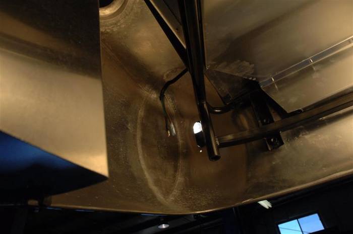
Here is a picture of the right rear tail light wires.
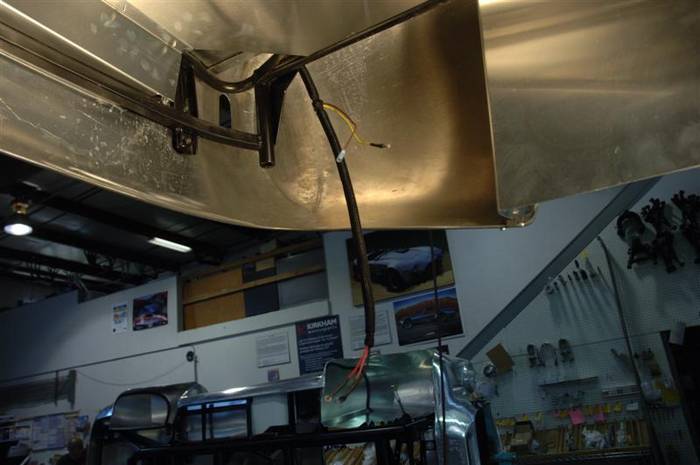
Here is a picture of the left rear tail light and fuel level sending unit wires.
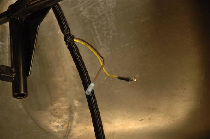
Close up of the tail light wires.
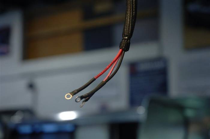
Close up of the fuel level sending unit wires.
Last edited by David Kirkham; 07-02-2007 at 01:53 PM..
|
-
Advertising


06-30-2007, 07:06 PM
|
 |
CC Member

|
|
|
Join Date: Mar 2001
Location: Provo,
Ut
Cobra Make, Engine: Kirkham, 427
Posts: 6,990
|
|

 Not Ranked
place holder for fuel sender hook up
Last edited by David Kirkham; 07-03-2007 at 09:30 AM..
|

06-30-2007, 07:30 PM
|
 |
CC Member

|
|
|
Join Date: Mar 2001
Location: Provo,
Ut
Cobra Make, Engine: Kirkham, 427
Posts: 6,990
|
|

 Not Ranked
place holder for license plate light hook up
Last edited by David Kirkham; 07-03-2007 at 09:30 AM..
|

06-30-2007, 07:36 PM
|
 |
CC Member

|
|
|
Join Date: Mar 2001
Location: Provo,
Ut
Cobra Make, Engine: Kirkham, 427
Posts: 6,990
|
|

 Not Ranked

On the brake pedal box.
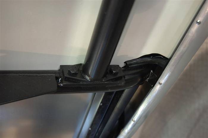
Here is a picture of the brake pedal box. In original Cobras the brake pedal box was not removable. Worse, the bottom of the pedal box was solid. The bottom didn't come off. It is VERY common for current owners of original cars to cut out the bottom of their pedal boxes so they can work on them. It is a most miserable chore to have to assemble a pedal box from inside the cockpit when the steering wheel is hitting you in the back and the gear shift lever is stuck in places I would rather not remember. Next time I have to install a pedal box in an original car I will hire someone from Cirque du Soleil to do it for me.
Anyway, here is what the bottom of our box looks like. It looks just like an original one, except we can unbolt ours and we rivet an aluminum access cover on the bottom of ours.

This is where we bolt the pedal box onto the car. There are two bolts in the rear (shown in the picture) and two bolts in the front. (not shown...at least yet).
Also, I had to take this picture from another one of our cars (Bobby Rahal's car  ) because my guys are bolting parts on faster than I can type!
Last edited by David Kirkham; 07-03-2007 at 09:44 AM..
|

06-30-2007, 07:43 PM
|
 |
CC Member

|
|
|
Join Date: Mar 2001
Location: Provo,
Ut
Cobra Make, Engine: Kirkham, 427
Posts: 6,990
|
|

 Not Ranked
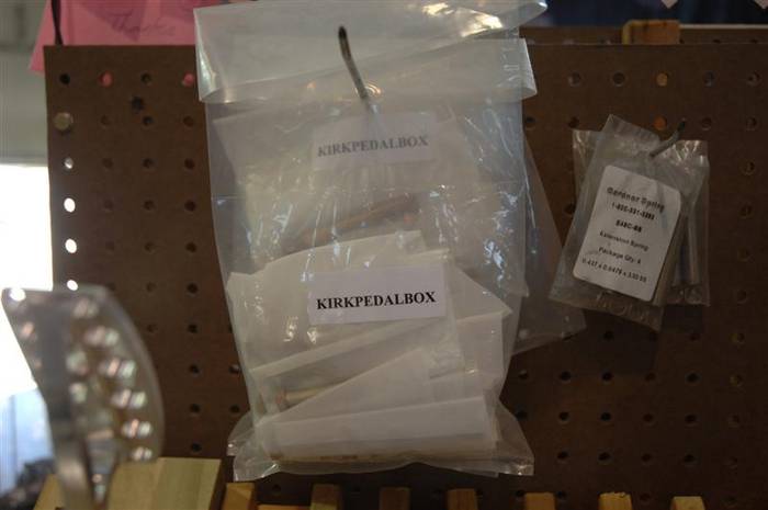
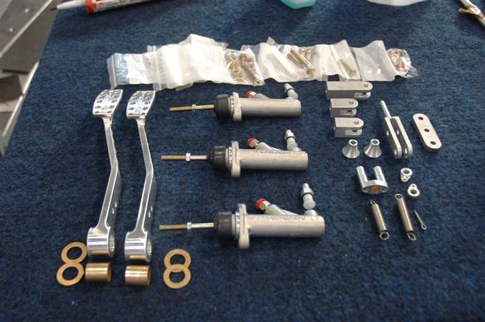
Here are all the pieces you will need to complete your pedal box.
Here are your bolts.
Here are your parts. We call them the pedal box guts.
If you look closely at the brake and clutch pedal arms, you can see we drilled two holes in them. That way both pedals can be used for either the brake or the clutch arm. The upper hole (the one towards the part you push on with your foot) is used to hook to the clutch master cylinder. The lower hole is used to hook to the brake master cylinders balance bar assembly.
Last edited by David Kirkham; 07-03-2007 at 09:49 AM..
|

06-30-2007, 08:09 PM
|
 |
CC Member

|
|
|
Join Date: Mar 2001
Location: Provo,
Ut
Cobra Make, Engine: Kirkham, 427
Posts: 6,990
|
|

 Not Ranked

In this picture you can see 3 master cylinders. The one on the left (in the picture) is for the clutch. The one closest to you on the right (in the picture) is the FRONT brake master cylinder. The one furthest away from you on the right (in the picture) is the rear master cylinder. If you read the size on the master cylinder for the front brake master cylinder you can see it reads .700 or 11/16" bore.
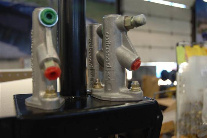
Rear brake master cylinder is .750 or 3/4" bore.

The clutch master cylinder is .700 or 11/16"--just like the front brake master cylinder.
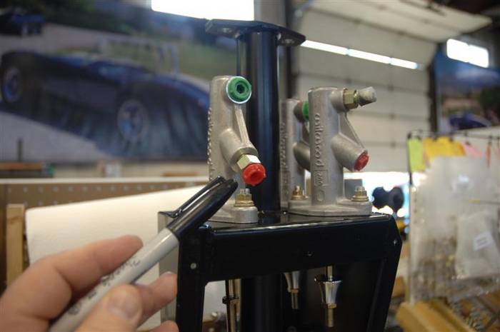
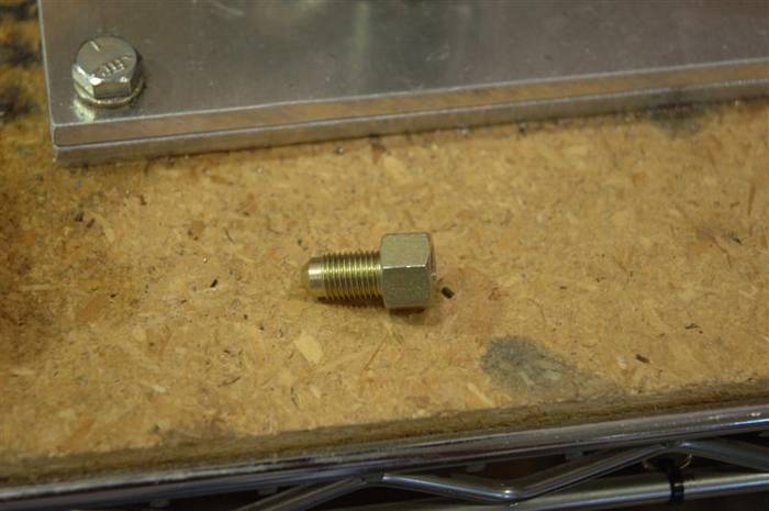
You can see in the below picture a little fitting that comes on all of the Wilwood master cylinders--straight out of the box. (I am pointing to it in the above picture). We throw them straight in the trash. You won't need them. Also, Joe got a little bit ahead of me assembling this pedal box and you can see the front brake master cylinder already has the brake reservoir fitting in it. On the master cylinder, the front opening (the one furthest away from the push rod) is a #4 o-ring boss fitting. The other side of the fitting is a #4 JIC which connects to the brake reservoir cans. There is no pressure on this fitting. It is simply where the brake fluid enters the master cylinder from the brake reservoir cans. If you get the billet reservoir can option on our list, then your brake fluid will not be rusty when it enters here. 
Last edited by David Kirkham; 07-02-2007 at 01:39 PM..
|

06-30-2007, 08:12 PM
|
 |
CC Member

|
|
|
Join Date: Mar 2001
Location: Provo,
Ut
Cobra Make, Engine: Kirkham, 427
Posts: 6,990
|
|

 Not Ranked

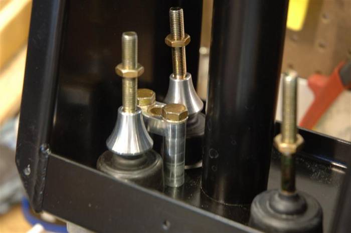
After you get your master cylinders bolted in, you will want to put you "bell stops" on your brake master cylinders. The bell stops are a fail safe device. They are there in case of failure of one master cylinders. If one of the master cylinders fails, then it will no longer offer pressure against the balance bar and all of the brake pedal travel will then go to the failed master cylinder. This is a good way to meet your Maker very unexpectedly--or at least to ruin the leather in your seat. Under failed master cylinder conditions, the bell stop only lets the failed master cylinder push rod engage so far before it stops (hence the name) and forces the balance bar to act on the other cylinder. Don't forget them or someone on this forum (probably Jamo) will nominate you for the Darwin awards.
In between the master cylinders you can see the "brake guide." There is a long pin on the balance bar fork that goes into this bushing. The guide pin keeps the brakes aligned so they work properly. If you forget to put this piece in the brakes will jam and Jamo will be posting about you.
Last edited by David Kirkham; 07-03-2007 at 09:56 AM..
|

06-30-2007, 08:33 PM
|
 |
CC Member

|
|
|
Join Date: Mar 2001
Location: Provo,
Ut
Cobra Make, Engine: Kirkham, 427
Posts: 6,990
|
|

 Not Ranked
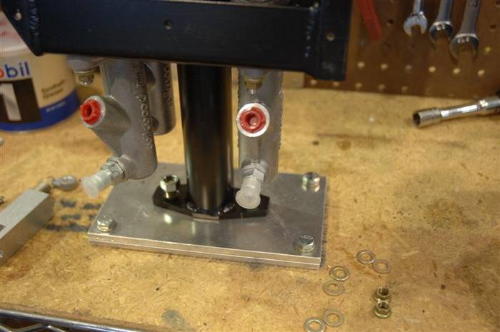
Here the #4 o-ring boss to #4 JIC adapters are fitted into the master cylinders. You have to be VERY careful when you install them to not cut the o-rings or they WILL leak!
Last edited by David Kirkham; 07-02-2007 at 12:47 PM..
|

06-30-2007, 08:40 PM
|
 |
CC Member

|
|
|
Join Date: Mar 2001
Location: Provo,
Ut
Cobra Make, Engine: Kirkham, 427
Posts: 6,990
|
|

 Not Ranked
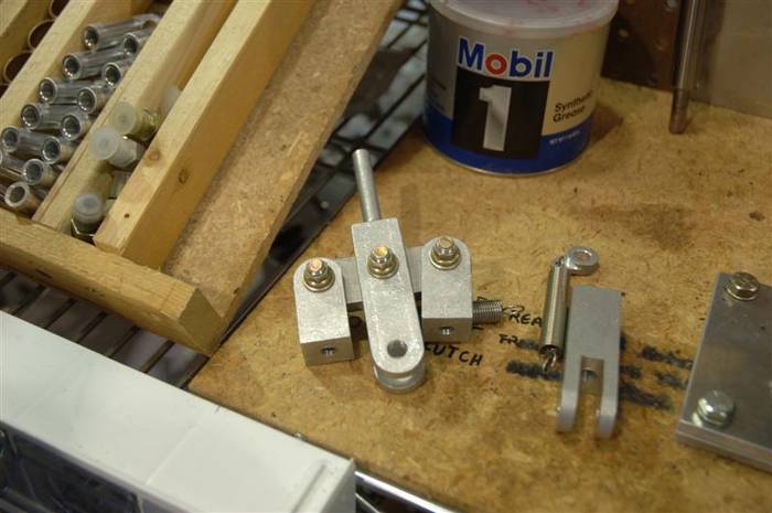
This is how you assemble the brake balance bar before it goes in. The actual balance bar is made out of 304 stainless and we cut it right here on our water jet.
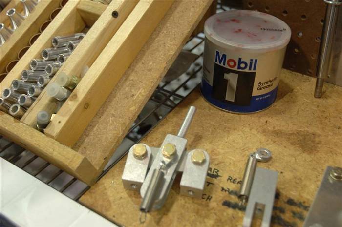
Here is a picture of the other side of the balance bar--showing the brake return spring bracket that bolts into the middle of the balance bar.
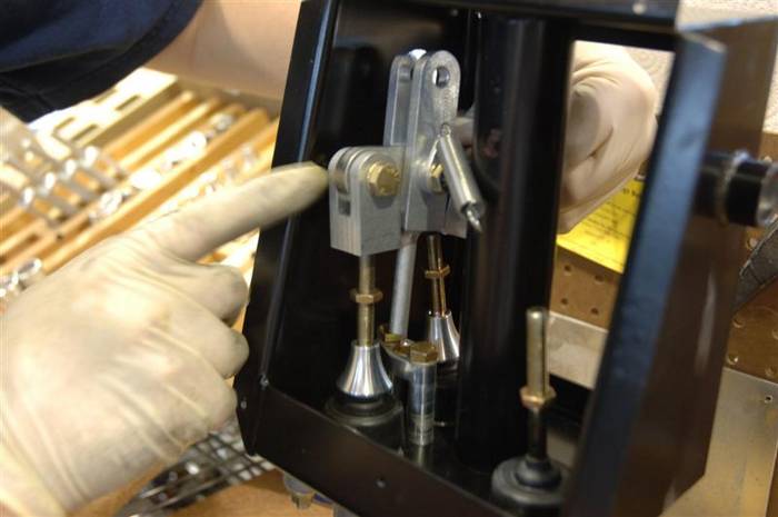
Here Joe is putting in the bias bar. MAKE SURE THE SHAFT GOES INTO THE GUIDE BUSHING!!! It looks like in the photo that Joe is a little bit off, but he actually is not. You have to screw the clevis forks on the balance bar onto the push rods and it flops all over the place while you do it. If you don't want your pedal box guts to flop all over the place when everything is finally bolted together then MAKE SURE THE SHAFT ON THE BALANCE BAR FORK GOES INTO THE GUIDE BUSHING!!! It is worth repeating.
Last edited by David Kirkham; 07-03-2007 at 09:57 AM..
|

06-30-2007, 08:41 PM
|
 |
CC Member

|
|
|
Join Date: Mar 2001
Location: Provo,
Ut
Cobra Make, Engine: Kirkham, 427
Posts: 6,990
|
|

 Not Ranked
Next, put the pedals in.
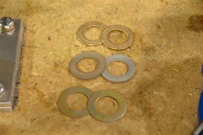
Notice in the below picture, Joe used shims on the brake pedal to get it all lined up properly. THIS IS CRITICAL!!! You have to work the brake pedals to make sure the guide pin slides freely and doesn't bind in the guide bushing. The bronze thrust washers need to be placed on both sides of the brake or clutch pedal. Any shims to straighten things out the go outside the bronze thrust washers.

Here is a picture of the shims. You can see the bronze thrust washers in the top of the photo. He selected the right thickness and shimmed everything perfect. When we send you the "Car in a box" we send you extra shims. You will not use all of them! Don't try! They will not all fit. We give you various thicknesses so you can line the balance bar fork shaft up perfectly.
Last edited by David Kirkham; 07-03-2007 at 09:59 AM..
|

06-30-2007, 08:45 PM
|
 |
CC Member

|
|
|
Join Date: Mar 2001
Location: Provo,
Ut
Cobra Make, Engine: Kirkham, 427
Posts: 6,990
|
|

 Not Ranked

Here is another angle view of the box with the pedals in it.
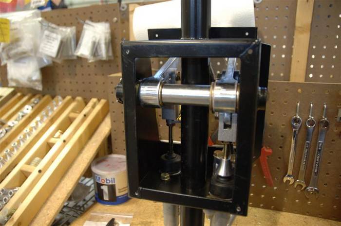
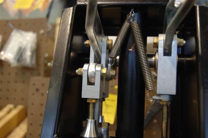
Here is a picture of the top of the box. Here you can see the little return spring billet bracket (same as the one on the balance bar) that has to be put on the clutch push rod before you screw the clutch master cylinder push rod on to the clutch fork clevis.
Also, you can see how we run the brake and clutch return springs. The brake return spring is CRITICAL to the functioning of the brakes. If you have a brake master cylinder failure, or if you develop a leak, the brake pedal will remain on the floor (along with your jaw) and will not return back up to so you can pump the brakes and get them to stop you before you run out of straight and have to turn. The spring forces the brake pedal to return in case of an emergency failure in the system. If you leave the clutch spring out, you will get stuck on the side of the road if something fails. If you leave the brake pedal return spring out and something goes wrong, you too will be stuck on the road--and the ambulance driver will scrape you OFF the road to haul you away. It is a Darwin offense to leave it out! Finally, in the back of the pedal box, we simply drill a hole and put a cotter pin in to hold the other side of the clutch and brake pedal return springs.
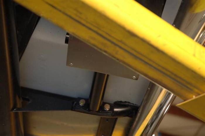
Here we have riveted the bottom of the pedal box back on and it is bolted back into place. We even put new bolts back into the holes.
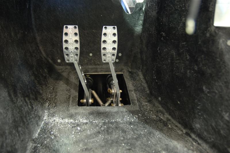
Top view of the newly installed pedal box.
Last edited by David Kirkham; 07-03-2007 at 10:03 AM..
|

06-30-2007, 08:49 PM
|
 |
CC Member

|
|
|
Join Date: Mar 2001
Location: Provo,
Ut
Cobra Make, Engine: Kirkham, 427
Posts: 6,990
|
|

 Not Ranked

Now you can bolt in your wiper system. First, you will need to put the wiper cable into the wiper motor. Then assemble the wiper motor bracket LOOSELY onto the wiper motor with the stainless steel (we like stainless steel) hose clamps. Then, locate the 3 tubes that come with the system. Take the tube with the nut on one end (the one with the BIG bend in it) thread it over the cable, and screw it onto the wiper motor. It only needs to be finger tight! Do not tighten it up with a wrench!!! You will jam the wiper cable in the housing and then you will "let the smoke out" of the wiper motor and you may have to call Frozone to put out any fire that may start.
Thread the tube and cable through the OUTBOARD hole above the left foot box (that is the hole you DIDN'T string the wiring harness through!) and into the cockpit. While it is still loose, plug in the wiper motor wires. It is MUCH easier now than later (unless you can convince Elastigirl to do it for you).
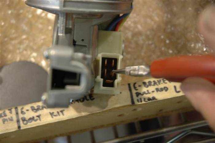
Plug the blue with white stripe wire in here:

Plug the solid blue wire in here:
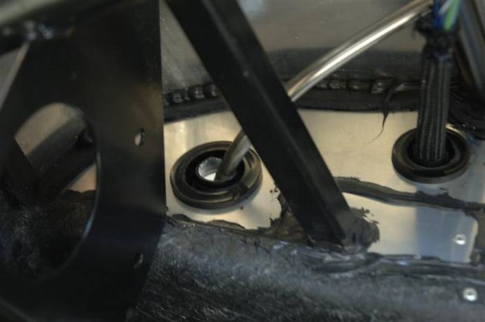
Thread the wiper cable and the 1st bent tube through this hole. Now, a lot of you guys (because you are very smart and have been reading EVERYTHING I have written) are going to post nasty comments on the QUESTIONS thread saying, "HEY DAVID, LOOKS LIKE YOU HAVE A BLOW TORCH HOLE IN THAT GROMMET THERE!" GOOD! I am glad you have been reading. But, have no fear, we are going to run a WHOLE bunch of dash sending units through that grommet to fill up the hole. By the time we are done with all the wires and sending unit plugs, you will wish the hole were BIGGER!
Bolt down the wiper motor into the top of the foot box.

Slide the tube with the slight bend in it between the wiper wheel boxes and tighten them up. Put the short tube on the right end of the right wheel box and tighten everything up. Again, you don't want to make things in the wiper department too tight.

Last edited by David Kirkham; 07-02-2007 at 11:46 AM..
|

07-02-2007, 11:05 AM
|
 |
CC Member

|
|
|
Join Date: Mar 2001
Location: Provo,
Ut
Cobra Make, Engine: Kirkham, 427
Posts: 6,990
|
|

 Not Ranked
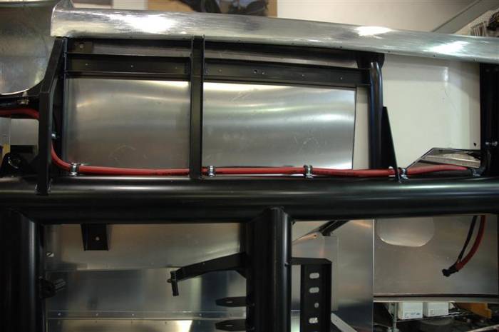
Here are the pictures for the routing of the battery cables. Make sure you keep them tight to the frame because the rear suspension and tire swings in this area. I took these pictures on another car we have on a rotisserie because it is easier to see.
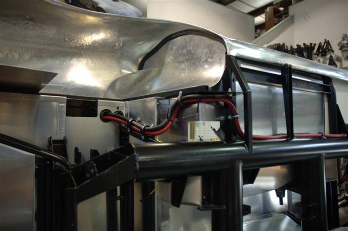
Here you can see where we rivet down the wiring harness and the battery cables.
Last edited by David Kirkham; 07-02-2007 at 11:11 AM..
|

07-02-2007, 12:42 PM
|
 |
CC Member

|
|
|
Join Date: Mar 2001
Location: Provo,
Ut
Cobra Make, Engine: Kirkham, 427
Posts: 6,990
|
|

 Not Ranked

As you can see, we relocated the batteries from behind the passenger seat to the trunk of the car. Original 427 S/C Shelby Cobras, as you all probably know, had the batteries behind the passenger's seat. I say "batteries" because original Cobras had two 12 volt batteries (hooked up in parallel). The batteries were placed behind the seats because they were race cars and they wanted to get to the batteries as easily as possible during testing, racing, etc. Also, at the time, they didn't care much about driver safety or whether or not he got something so "insignificant" as SULPHURIC ACID (battery acid) splashed on him. Today we worry about those things, (and the lawyers who tend to follow the above ambulances), so we try as hard as we can to be as safe as possible.
Over the years I have wondered about the wisdom of having batteries right beside you--especially in case of an accident. So, we decided to take the batteries and replace them with a single, new, modern, military unit. We still keep the battery on the passenger side of the car to help maintain weight balance against our ever expanding waist lines. We save 20 pounds (still trying to get below 2000 lbs!) as well by going to a single battery. We certainly didn't go to one battery to save money, the Odyssey battery is almost $200. Further, we don't sell the battery with the base model car because it is not good for batteries to sit around. Who knows how long it will take you to finish your assembly (just ask Ron Richards) and it is always best to have a fresh battery when you fire up your Chariot of Fire for the first time.
Here is a picture of our latest billet battery box.
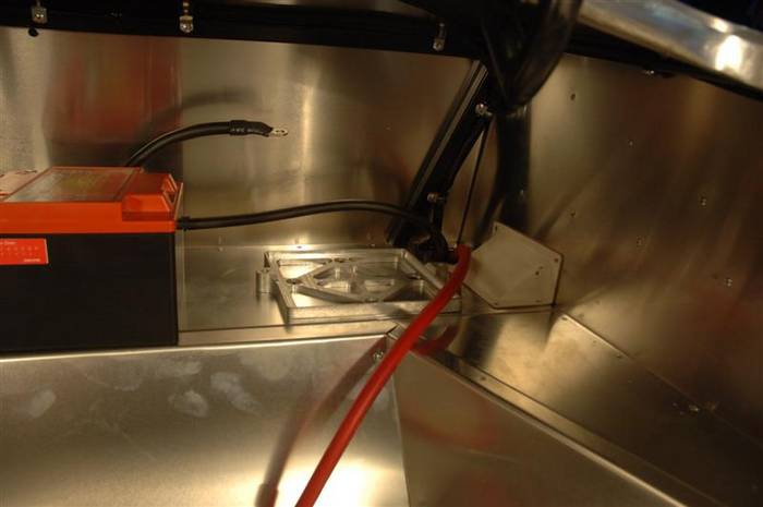
Here is a close up of the 4 bolts that hold the box in.

Last edited by David Kirkham; 07-03-2007 at 10:09 AM..
|

07-02-2007, 01:09 PM
|
 |
CC Member

|
|
|
Join Date: Mar 2001
Location: Provo,
Ut
Cobra Make, Engine: Kirkham, 427
Posts: 6,990
|
|

 Not Ranked
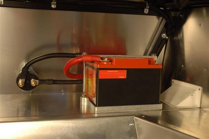
Here is a picture of our latest Odyssey battery. Notice the battery cut off switch that we mounted on the rear firewall between the seats.
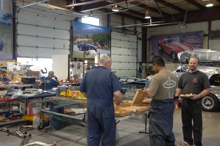
Now it is about time for a nice Kirkham Motorsports PIZZA PARTY!!! Thanks to Rob Simoes! Thank you.
This is also a GOOD time to grab yourself some pizza!
You can see the stainless header prototypes in the lower left hand part of the photo...coming up soon!
Last edited by David Kirkham; 07-02-2007 at 02:38 PM..
|

07-02-2007, 05:44 PM
|
 |
CC Member

|
|
|
Join Date: Mar 2001
Location: Provo,
Ut
Cobra Make, Engine: Kirkham, 427
Posts: 6,990
|
|

 Not Ranked
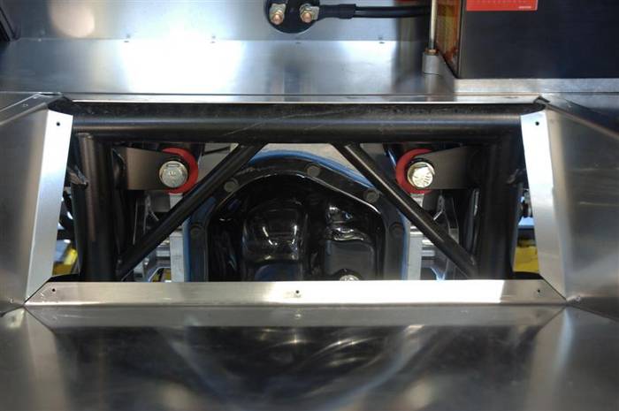
Here is a picture of the aluminum Kirkham differential installed in the car. You want to install the differential now because you don't have the suspension banging you in the head while you are crawling around under the car. Every time someone in the shop bangs their head someone always shouts out, "COBRA BITE!" It is MUCH funner to yell "COBRA BITE" than it is to hear it.
Last edited by David Kirkham; 07-03-2007 at 10:12 AM..
|

07-02-2007, 05:55 PM
|
 |
CC Member

|
|
|
Join Date: Mar 2001
Location: Provo,
Ut
Cobra Make, Engine: Kirkham, 427
Posts: 6,990
|
|

 Not Ranked
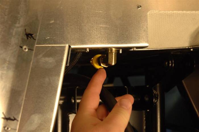
This is a picture of the differential breather hose where it goes through the trunk paneling to connect to the catch can which is in the trunk. The breather can is now mounted up high in the trunk. The hose is not yet connected to the 90 degree bulkhead fitting in the panel as you can see the hose (too long and yet to be cut) is still in my fingers. The hose and 90 degree bulkhead fitting must be oriented the same way they are oriented in the picture or they will interfere with the travel of the rear upper control arm at full bounce.
Last edited by David Kirkham; 07-02-2007 at 05:58 PM..
|

07-02-2007, 07:28 PM
|
 |
CC Member

|
|
|
Join Date: Mar 2001
Location: Provo,
Ut
Cobra Make, Engine: Kirkham, 427
Posts: 6,990
|
|

 Not Ranked
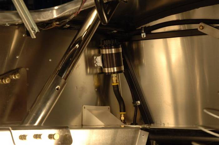
This is how the differential breather mounts. You want the breather to be mounted as high as possible.
 |

07-02-2007, 07:30 PM
|
 |
CC Member

|
|
|
Join Date: Mar 2001
Location: Provo,
Ut
Cobra Make, Engine: Kirkham, 427
Posts: 6,990
|
|

 Not Ranked
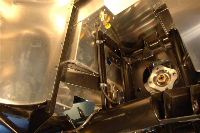
Differential breather hose hooked up and run properly.
 |

07-02-2007, 07:32 PM
|
 |
CC Member

|
|
|
Join Date: Mar 2001
Location: Provo,
Ut
Cobra Make, Engine: Kirkham, 427
Posts: 6,990
|
|

 Not Ranked
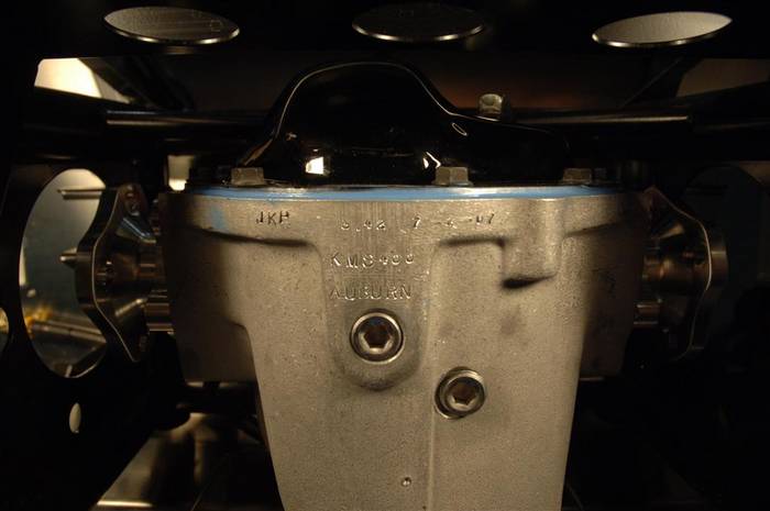
You can see the stampings in the back of all of our differentials. We stamp them with the date, who made the, the type of locking differential (all of our differentials are lockers but there are several different types), and the gear ratio of the ring and pinion.
Last edited by David Kirkham; 07-02-2007 at 07:52 PM..
|
 Posting Rules
|
You may not post new threads
You may not post replies
You may not post attachments
You may not edit your posts
HTML code is Off
|
|
|
All times are GMT -7. The time now is 02:36 AM.
|
|











 2Likes


 ) because my guys are bolting parts on faster than I can type!
 Linear Mode


