Terry, got back to the office later this afternoon (photos and text were on the wrong laptop

).
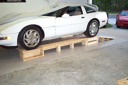
Here are a few photos and the original text that I plucked off of corvetteforum.com some months ago.....


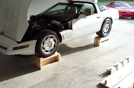
As you can see, the ramps themselves come apart and leave just the pedestals. This allows for easy access underneath from the sides. I have a few more pics available, but these pretty much show what they look like and the (long) description below tells you how to build them.
RAMPS
Below is the list of materials & a description of the parts. Unless noted I used 3" grabber screws (these have the course drywall type thread on them.) I predrilled all the boards. I drilled the pass through board & didn't drill the anchoring board. I can't think of a good way to explain this. My total cost was just under $75.00. I will get some close ups of the pedestals & post them tonight or tomorrow. Note: I made my fronts & rears different heights to accommodate the slight slope that my garage has. If you don't care about compensating for or if you don't have a slope you can make the fronts & rears the same (either design).
Materials required per SIDE
Front Pedestal
2pcs - 2 "x 10" x 23" (top & bottom)
2pcs - 2" x 6" x approx. 9.5" (width of 2"x 10")
1pc - 2" x 6" x 20"
1pc - 2" x 4" x approx. 9.5" (front stop)
2pc - 2" x 4" x approx. 7" (used to support bridges)
Attach short 2"x 6" pcs to the long 2" x 6" form an "I" so the 6" part is up/down. Next attach a 2" x 10" to the top and bottom the attach the stop to the top front of the pedestal & the last two 2" x 4" to the rear of the stop at the edges for the bridge support.
Rear Pedestal
2pcs - 2 "x 10" x 23" (top & bottom)
2pcs - 2 "x 10" x approx. 9.5" (width of 2"x 10")
4pcs - 2" x 4" x 20" (side supports)
4pc - 2" x 4" x approx. 9.25" (used to support bridges & ramps)
Attach the 2" x 4" to each corner of the 9.5" 2" x 10" (the cut part of the 2" x 10" should be on the sides of the unit not up/down. The 2" x 4" need to be installed so the 4" part will be up/down when the pedestal is in use. Put the top on the unit & the front & rear bridge/ ramp supports.
Bridges
You will need to do some math on this one. Mine are 6' but really need to be about 6'2". Measure the distance of the wheel base (center of hub to center of hub). Subtract 23" from this number & it will tell you how long the bridges need to be. Buy 8' lengths & you will be covered.
1pc - 2" x 10" x measurement found above
1pc - 2" x 4" x measurement found above
4pcs - 2" x 4" x 9.25"
2pcs - 2"x 4" x 5.75"
Attach the 2" x 4" to the bottom of the 2" x 10" centered left to right.
Build the bridge supports as shown in the last picture (they are at the top). 2 long 2" x 4"s with the short one sandwiched between. I made these a little longer than this to start with and trimmed them down for a good solid fit. I marked the bridges in 1/3 of the way from each end also so I would know where the supports need to be placed.
Ramps
Again you will need to do some measuring. Place a pedestal in front of the car. Slide it toward or away from the car until you find the minimum distance the unit needs to be from the car to allow the air dam to clear. Hint: I cheated a shade. My driveway has a slight incline & I used it to my advantage. By approaching the system with it uphill the ramps can be made a little shorter. If you would ever be using the system in a downhill situation take that into consideration.
1pc 2" x 10" x 8' (cut down to above figures)
The ramp supports were made from the drops from the other pcs. I have no clue what they measure at the moment. I used a couple pieces of 2" x 6" & several 2" x 4"s.
The system in pinned together with .375" x 4" bolts. Two on the front & rear of each bridge & two on each ramp. Before drilling the holes for the pins put the system together & mark the ramps, bridges, & pedestals to each other, that way it will go back together later on with out confusion. The bridge support holes are drilled straight down toward the floor while the ramp pin holes are drilled perpendicular to the ramp angle.
Cut angles on the ramps supports on the rear pedestals for a bigger contact area. I also cut the same angle on the front units so I could use them alone if needed.
I think that should get everyone close. Also I'm doing this from memory & quickly so let me know what I need to clarify....if anything
If you want to add more strength you can seal the whole thing in epoxy.
This would help stop any splits.
Also try to keep the grain of the wood parallel to the ground so that's it's in compression.
It is std. 2x material from Home Depot. "Finished" stock is 1.5" x 9.25" on a 2" x 10"
Epoxy would help. A grip modifier would be need on the driving surfaces.
I measured the distance between the insides of the tires & added 2" to it & placed the ramps that far apart. (note: the fronts & backs ARE different). I screwed a 2" x 4" across the pairs of pedestals to maintain the distance. That's what I get from working from my pictures & memory !
Trust me the system won't collapse. I tossed a pair of 2" x 4" in front of the front pedestals & braced off the back wall. Later I plan on putting pinning holes in the floor.


 ).
).

 Linear Mode


