A lesser known option for an ERA is the aluminum engine panel set. These panels trim out over the engine bay fiberglass & accurately replicate an original car. They aren’t cheap, & with the new re-design ERA has recently completed, they are going to be “no more” when current supplies are gone. ERA has 1 or 2 sets left for retrofits & won’t be making any more. (Actually I have template if there is a sudden rush on them, so let me know if the factory can’t help you.

)
Apologies for some of the pix being blurry – a camera glitch that required it to be sent back to the factory. Anyway, the process to install is as follows:
Step 1 – Remove engine. Engage 14 year old son in process for “quality bonding time”.

Note browning of the fiberglass (visible and labeled in the lower part of the picture) - this upgrade cleans it up. I had installed ERA’s heat deflector panels earlier (labeled in the pic).

Passenger side – not as bad, but still there.

The set consists of 4 panels. The smaller panels (laying on floor) are mirror image – will fit left or right side (except that one side is a finish side, the other is not, so they only go in 1 way), longer panels are side-specific. Note – the longer panels start life as 1 piece & will be cut in ½ at their narrowest point – same as the original car. Green color is a protective plastic film that is removed at the end.
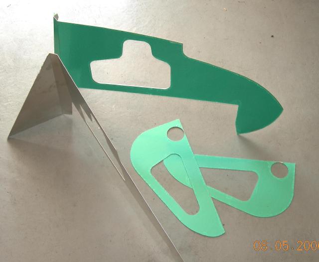
Looking down on the longer side panels. Panels have some tricky bends to fit tight.

After engine removal, remove header pipes, cold air hoses, rad, & loosen rad mounting brackets:


While the rad support bracket is loose, now is a good time to check for wire chafing where the headlight wires pass through the rad bracket. Mine had the ever so slight beginnings of some chaffing, and I fixed this by putting on a small discreet piece of duct tape along the top edge of the rad frame. Suggestion to ERA – a small piece of trim foam of some sort along here is a good idea.
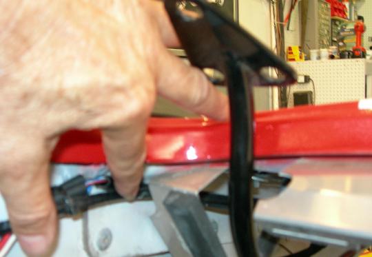
Panel test fit: Uh-oh. The heat deflector plate screw falls right into the middle of the where the wheel well cooling vent hole will go.

Hmm…calling Bob Putnam?? Note duct tape to temporarily hold the panel – a great way to have a second set of hands.

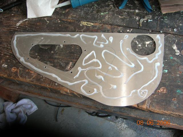
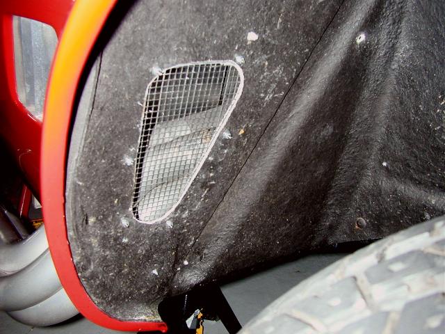
My decision was: I would recreate the panels and make the wheel well vent hole smaller. The original sized hole can be seen below traced onto my new panel, as well as my new smaller hole: I also enlarged the cold air vent holes provided by ERA in the panels – the ones on the panels are a good 3/8” smaller than the existing holes in the fiberglass – I wasn’t gonna spend another $20.00 for another hole saw, so the hole is a bit ragged – it doesn’t show though, so no big deal. A lot of work to recreate these.
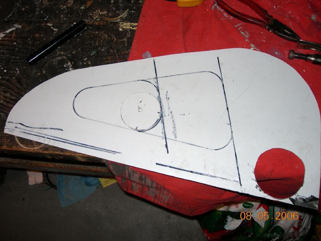
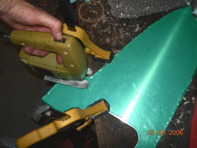
Cutting the new panels – clamp your work well – use a saber saw & a sharp blade. Take your time.

The original ERA panel, & my new one. Flip it over and do another (note – the aluminum I bought at the local aluminum supplier has white film instead of green). Also note the template for the new screen holder – I will transfer it from cardboard into aluminum later.

Test fit the panel – double & triple check your work – use duct tape to hold it in place. Trace. Next step is you will be cutting into the factory fiberglass fenderwells – you can’t afford a boo boo. You need to be totally sure of your work – cutting into my baby!! Unnnhh, I hope its right! These have to be cut in from the wheel well side for saw access. This meant a lot of fiddling using small drill holes as a guide (visible in the pic) - be sure the positioning is transferred correctly to the back side. Mesh to add later is available from McMaster Carr. I used stainless steel, .224” screen hole size.

Now you are ready to start installing the panels. Tape off the paint – these panels are sharp, and big – there isn’t a lot of room in there – a small scratch is all it takes:
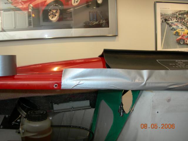
Once the panel is ready to go in, silicone the back of it before riveting – this will eliminate rattles. Use the 3” dia cold air vent holes as a guide and set it in place. Rivet the panel using 1/8” rivets - it only takes a few – no need to overdo it.
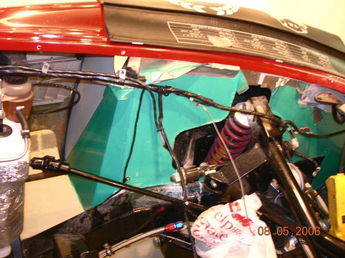
Onto the next panel. The drivers side is much harder than the passenger side – you have to remove wiring, and the steering column is there. Test fit the panel – the
critical fit line is along the top where the panels meet the fender. The panel may bind down low by the frame – check it and fit it – again – and again - take your time…

Yup, needs a bit of trimming. Measure 3 times, cut once.
The fiberglass was showing around the shock tower opening, and had to be trimmed backwith a saber saw. By now, cutting up my ERA was second nature.

OK – making progress – the larger side panel is now cut in half and both panels have to be worked in together. It is necessary to temporarily remove the protective duct tape to verify the fit. Also note the green film is peeled back a bit to check the fit. Note in this pic I was checking the fit of the long large panel the with the smaller vent panel before I had cut the cold air vent holes. The panels were fitted many times before finally getting it the way I wanted it.
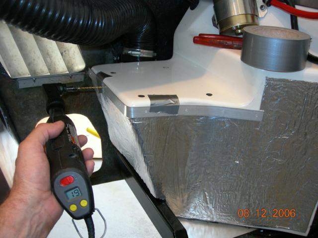
Getting access to all the necessary spots to rivet the panels is tricky, but do-able if you use a Dremmel tool with a 90 degree drill accessory. Note needle nose vice grips.

The front ½ of the long panel has to be fitted in the front as well – access through the front grill opening. (This is why you remove the rad bracket at the start). All existing holes for things like wiring looms for lights and screw holes for things like the hood support rod have to be transferred to the aluminum panels after fitting.

Visible progress at last. (damn camera!):

To copy the rivet pattern ERA uses, I took pictures from a car in ERA’s shop (Thanks ERA 728). This job is a lot easier to do while the car is brand new and under construction. Note the larger wheel well vent hole on 728.
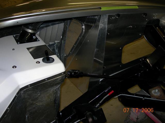
See the seam right above the frame where the panel is cut? (where the 4 rivets are below). Before I cut the panel, I had a discussion with ERA as to whether you could actually fit the panel as 1 piece if you only cut the bottom (that doesn’t show). ERA: “Why would you? The original cars had a seam there”. Me: “Uh, never mind”.

Moving on, it seemed like a good idea to replace the insulation on the footboxes while I was at it. First I created a pattern from cardbord reinforced with duct tape. Cut fit, cut fit, cut fit, ... (pic below) Template above, original insulation below. Insulation is available in rolls at Home Depot for about $15.00 – identical to the factory stuff.

This is a bigger job than it first appears – I was determined to keep my insulation 1 piece. The steering column has to be loosened from inside the car, the brake line has to pulled back. Dilling out of the cap strip below the steering column to remove the original insulation was tough – I think ERA must have used grade 8 rivets here! Also, the insulation has to be laid in exactly level, or you have to start over. But, the results are worth it.

Another upgrade that caught my eye at ERA was the use of an aluminum cap strip across the top of the insulation – a nice finishing touch. The aluminum is available at Lowes in a perfect size & thickness. My 90 degree Dremel was invaluable for this project. I didn't use my regular drill for any rivets or holes unless the size required the bigger drill.
Finally, reinstall the motor. Be careful to not damage the new insulation – use heavy cardboard duct taped in place – the biggest potential culprit for damage to the footbox insulation are the header pieces on the drivers side.
Results:
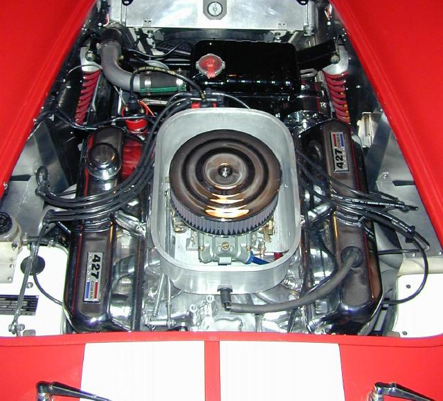
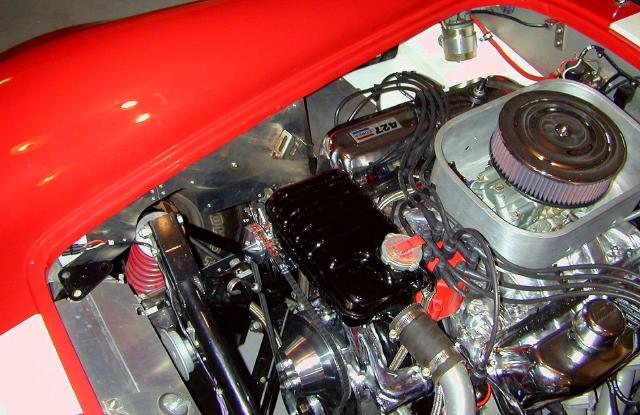
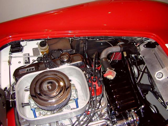
So, that wraps it up. This certainly isn’t a Saturday afternoon job, but, if your motor is out anyway, you have a good head start.
The results are awesome. I couldn’t be more pleased with my “aluminum ERA".


