 
 Main Menu
|
 Nevada Classics
|
 Advertise at CC
|
| S |
M |
T |
W |
T |
F |
S |
| |
|
|
|
|
|
1 |
| 2 |
3 |
4 |
5 |
6 |
7 |
8 |
| 9 |
10 |
11 |
12 |
13 |
14 |
15 |
| 16 |
17 |
18 |
19 |
20 |
21 |
22 |
| 23 |
24 |
25 |
26 |
27 |
28 |
|
|
 CC Advertisers
|
|
 23Likes 23Likes
-
 5
Post By MasterAnubis
-
 3
Post By MasterAnubis
-
 1
Post By eschaider
-
 3
Post By patrickt
-
 3
Post By MasterAnubis
-
 3
Post By MasterAnubis
-
 1
Post By MasterAnubis
-
 4
Post By MasterAnubis

07-24-2023, 10:39 PM
|
 |
CC Member

|
|
|
Join Date: Aug 2021
Location: Tempe,
AZ
Cobra Make, Engine:
Posts: 75
|
|

 Not Ranked
 Home build 427
I was trying to do this with a big upload of photos or videos. Well, I made one video and I didn't upload the ton of pictures I have. This is a long story so let's begin.
I have come a long way since opening up this can of worm and it's a list of mostly preparations. I.E. tools.
I became impressed with the knife makers belt grinders from Forged in Fire. So I made one.
I was needing a beadroller and was Jere Kirkpatrick gave me a bunch of ideas for one. I ordered the Woodward Fab one and proceeded to mod the daylights out of it. Then I needed an English wheel. I got some 3"x2-3/8" I beams from the cut-off at my local metal supply. I had limitations from length but I designed a good benchtop 3" wide 8" diameter wheel and spent the most time on the adjusting mechanism. I welded scrap discs from work together and made my upper wheel. That gave me a taste and I opted out of making the anvils, so I bought a set of Metal Ace anvil wheels. Once I boxed in the I beams, this became a very nice setup.
I bought the chassis and miscellaneous plans from Chuck Cobra and scored a fiberglass Shelby American body that was slightly damaged from hitting a wall at PIR.
I've been running small tests for the bodywork in 3003. I'll get some tests in with riveting and skinning soon.
This is the video of where I'm at with the pedal box. I could sneak this in without saying "I've started the chassis." Send Cut Send cut and bent these pieces.
https://youtu.be/qj7n1dcTaFs
I'll add the photos when I have more time.
__________________
Shawn
Tempe, AZ, USA
|

07-24-2023, 11:27 PM
|
 |
CC Member

|
|
|
Join Date: Feb 2006
Location: Gilroy,
CA
Cobra Make, Engine: SPF 2291, Whipple Blown & Injected 4V ModMotor
Posts: 2,738
|
|

 Not Ranked

Very nice job. Those kinds of parts always seem so simple when you first think about making them and then take on impressively complicated design attributes as the project moves forward. Your design and finished work product is quite impressive!
While I can appreciate the fabrication of individual bottom and side pieces that are welded together to create the pedal box, did you consider making the box out of a single sheet of metal?
The approach would mandate starting by laying out the floor dimensions and making square cutouts for the four sides you would bend upwards in a brake. After bending the sides upward you would bend the flange along the top edge on each of the four sides. Now you would be ready to weld the four corners and the foot box shape fabrication would essentially be complete.
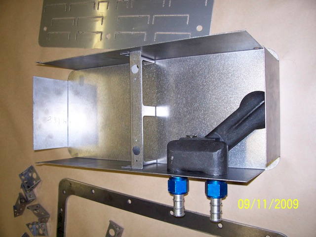
FWIW I didn't think of this approach, I'm not that good. A friend of mine, who is a sheet metal fabricator, that I had asked for help in building my oil pan, looked at my oil pan design (which I did the same way you did your foot pedal box) and asked me why I wanted to do this the hard way?
He then sketched up the 'easy way' on his MasterCam software to show me the route I could have taken design-wise. Here is a pic of the pan before welding the rounded corners in;
And this is what it looked like with the flange, trap door baffle and windage tray mounts in place;
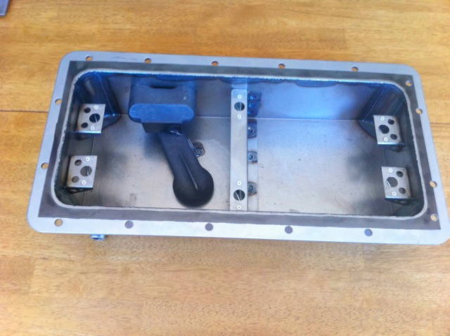
Less time spent welding and a more robust finished product, for when I screw up and bounce it off something it should not hit.
__________________
 Help them do what they would have done if they had known what they could do.
Last edited by eschaider; 07-25-2023 at 11:24 AM..
Reason: Spelling & Grammar
|

07-25-2023, 11:13 AM
|
 |
CC Member

|
|
|
Join Date: Aug 2021
Location: Tempe,
AZ
Cobra Make, Engine:
Posts: 75
|
|

 Not Ranked

Thanks!
The short answer is that is how AC made these boxes in the 60's.
All the bends in this box are as they were back then. The exception to the box is the bottom. The originals were a solid bottom that was part of the back panel.
The long answer is that I weighed the cost, originality, my capabilities and function. I can't comfortably cut or bend .074" steel this precisely right now.
The most common update I've seen to this box is making the bottom a removable panel for access to the pedals/mechanisms. Kirkham adds flanges to each side on the bottom and a cover, so that it's open and they only weld up the corners of the box.
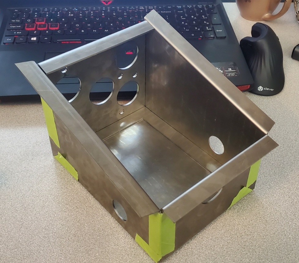
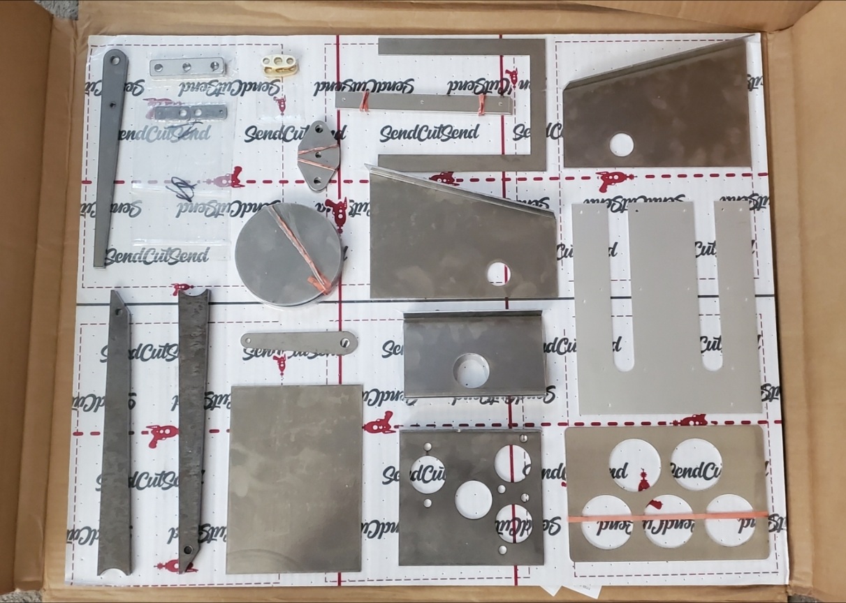
I opted for a weld in piece for the flanges. This thickness welds easy enough that it didn't seem to be a challenge. The front panel is thicker because it's essentially the bulkhead, so it wouldn't be part of the box anyway. I used Send Cut Send to cut and bend these pieces. I've never used then to bend and wasn't sure that the I could use their bend calculator right.
The box taped together for first test fit:
How I ordered the parts. Not all the holes are there. Some where made for placement so I could size them and others omitted so that I can place them myself after assembly.
The upside down look at the brake clevis guide:

Clevis pins without cotter pin holes. The two on the left are done, the two on the right need faced.

The clevises, pins and bell nuts:

The pedal arms were notched to bend then welded with a 1 inch offset.


.
__________________
Shawn
Tempe, AZ, USA
|

07-25-2023, 11:29 AM
|
 |
CC Member

|
|
|
Join Date: Feb 2006
Location: Gilroy,
CA
Cobra Make, Engine: SPF 2291, Whipple Blown & Injected 4V ModMotor
Posts: 2,738
|
|

 Not Ranked
I can better understand your fabrication decisions with the emphasis you placed on attention to originality, Shawn. Very impressive job and attention to detail — lots of effort and a beautifully fabricated pedal box!
__________________
 Help them do what they would have done if they had known what they could do.
|

07-25-2023, 12:08 PM
|
 |
Half-Ass Member

|
|
|
Join Date: Jun 2005
Cobra Make, Engine: ERA #732, 428FE (447 CID), TKO600, Solid Flat Tappet Cam, Tons of Aluminum
Posts: 22,017
|
|

 Not Ranked
That's beautiful work. If you do make your box tight as a drum I would still leave one tiny weep hole at the lowest point to tell you when you have a MC leak, kind of like your water pump.
|

07-25-2023, 12:09 PM
|
 |
CC Member

|
|
|
Join Date: Aug 2021
Location: Tempe,
AZ
Cobra Make, Engine:
Posts: 75
|
|

 Not Ranked
Thank you, again!
I have more pics uploaded that I can post now. The file size limit takes extra steps to get to.
The pedal springs took a few practice pieces but I'm pretty confident in making them now.
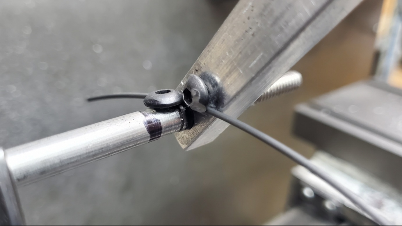
What's missing is the turning arm with the screw that wraps the wire around the mandrel. This is .055 music wire.

This pedal is on a scrap piece I had before I ordered the pedal arms. The pivot pin is stainless steel and needs drilled for cotter pins.

.
__________________
Shawn
Tempe, AZ, USA
|

07-26-2023, 08:14 AM
|
 |
CC Member

|
|
|
Join Date: Feb 2006
Location: Gilroy,
CA
Cobra Make, Engine: SPF 2291, Whipple Blown & Injected 4V ModMotor
Posts: 2,738
|
|

 Not Ranked
I was curious about how you made those springs, Shawn. Now I understand. Very crafty!
Was the music wire difficult to work with or pretty straightforward?
__________________
 Help them do what they would have done if they had known what they could do.
|

07-26-2023, 12:04 PM
|
 |
CC Member

|
|
|
Join Date: Aug 2021
Location: Tempe,
AZ
Cobra Make, Engine:
Posts: 75
|
|

 Not Ranked

Quote:
Originally Posted by eschaider

I was curious about how you made those springs, Shawn. Now I understand. Very crafty!
Was the music wire difficult to work with or pretty straightforward?
|
Bending it (this .055" music wire) was straight forward once I learned some of the rules. This is a torsion spring. Techniques vary with compression and extension springs.
-be careful with the removing the wire from the roll. It wants to unwind.
-cut off disc is a must to cut and deburr ends. No cutter will do well for long.
-deburr ends first. They will shank you.
-bending it is just overbending until it relaxes where you want it.
-bending tools need to clear the hold down screws if you want a tight winding. Both my hold down screws where trimmed considerably.
-the mandrel needs to be the same size or slightly larger than the pin.
-no lathe is needed. A bench vice would work for this spring just fine.
-keep the tension when winding.
-accuracy increased with practice.
-some straightening will help with precision too. The wire doesn't need to be laser straight.
-solid pliers will bend 90* well.
I started on a 1/4" mandrel just to play and used Vice Grips to hold it to the rod. Then I went to a slightly larger mandrel and got a 5/16 id on the coil. This was too small. The windings collapse when the spring is used and I couldn't get the pin through it. Using a 5/16" mandrel allowed the spring to relax larger and works great on a 5/16" pin. I made about a dozen springs before I got a pair I liked.
EDIT:
This Old Tony did a relevant video that shows almost exactly how I made the pedal springs. I used a hand turner.
Jump to: https://youtu.be/jAawhg6JtyY?t=440
Whole video: https://www.youtube.com/watch?v=jAawhg6JtyY
This is before I REALLY hacked up the screw heads. This is similar to some commercial spring tools.
.
__________________
Shawn
Tempe, AZ, USA
Last edited by MasterAnubis; 07-26-2023 at 01:07 PM..
|

07-31-2023, 04:36 PM
|
|
CC Member

|
|
|
Join Date: Dec 2004
Location: Colorado Springs,
Co
Cobra Make, Engine: Cobra FF5/BBM 482
Posts: 160
|
|

 Not Ranked
What suspension are you going to use
|

07-31-2023, 05:26 PM
|
 |
CC Member

|
|
|
Join Date: Aug 2021
Location: Tempe,
AZ
Cobra Make, Engine:
Posts: 75
|
|

 Not Ranked
Quote:
Originally Posted by feadam

What suspension are you going to use
|
The original style, in spirit.
I'll be using Delrin instead of the metalastic bushings that it calls for and adding any adjustability that I think it needs. C4 wheel bearings all around with Mustang II uprights(for the dimensions). Jag pumpkin with outboard brakes. I'll see about using CV joints instead of U-joints in the half shafts. Those will be figured out when I have final lengths since they are slip shafts.
Wilwood is good about supplying dimensions of their parts. So, I've been able to model some of the hub fitment of brakes and rims. There are several advantages to go with lower profile tires but I won't go wild. I have to weigh all of that.
This is most of my preliminary rear upright design that will use the C4 bearing and weld together. There will be plate covering the inside.

.
__________________
Shawn
Tempe, AZ, USA
|

08-27-2024, 10:10 PM
|
 |
CC Member

|
|
|
Join Date: Aug 2021
Location: Tempe,
AZ
Cobra Make, Engine:
Posts: 75
|
|

 Not Ranked

Holy cow! It's been over a year already since I started this thread!
I've got quite a bit of progress. I'll keep this on short in favor of making a video log. The way the forum host pictures is a little cumbersome to what I'm used to, too.
I'll throw up the pics I've had sitting here to show.
My first body piece test, My 'flexible shape pattern' to make the second test piece, the shrinker 'stump' I made using cutting board techniques, My english wheel I designed an built, and my beading machine that I moded with every mod a modder could mod.

I had scored with this Shelby American fiberglass race body that was dinged up at PIR.

I also scored these NOS Shelby American footwells and made a good freind in the process.

Here is the pedal box setup now.
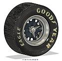
My models and renderings. I modeled up Vintage Wheels rims and was actually able to find a used set of Superformance wheels from a 2005 car. They are 5 pin with the corrects size and offset, 7.5" and 9.5"
Frame and chassis.
  
I got this axle assembly from an XJ12. The gears are pretty high and I may not use it, but I have it.
 
This is a comparison of the wheels in CAD vs real life with a foam prototype.
I designed this one for C7 wheel bearings but the Superformance wheels us the ford pattern. I've since redesigned it for Mustang 2020 bearings. The caveate is that they have 14mm x 1.5mm thread. The studs will get replaced with shortened ARP 100-7703 studs that fit the pins I'm getting from Vintage Wheels with the adapter set.

That's it for now and I will be getting more parts and starting the main rails in the next couple of weeks.
-Shawn
.
__________________
Shawn
Tempe, AZ, USA
|
 Posting Rules
|
You may not post new threads
You may not post replies
You may not post attachments
You may not edit your posts
HTML code is Off
|
|
|
All times are GMT -7. The time now is 12:05 PM.
Links monetized by VigLink
|


